Method and circuit for measuring the optical modulation amplitude (OMA) in the operating region of a laser diode

a laser diode and optical modulation amplitude technology, applied in the direction of individual semiconductor device testing, semiconductor lasers, instruments, etc., can solve the problems of inaccurate operation of laser diodes, errors in average optical power,

Inactive Publication Date: 2003-05-15
ANALOG DEVICES INC
View PDF9 Cites 25 Cited by
  • Summary
  • Abstract
  • Description
  • Claims
  • Application Information

AI Technical Summary

Problems solved by technology

It will be appreciated that errors in the average optical power will be present due to MPD tracking errors and control loop effects such as the temperature coefficient of R.sub.pset and the input offset voltage of the control loop input stage.
A disadvantage of such circuits is that they tend to be inaccurate.
Thus, any corrections made to correct the OMA based on the operating temperature of the laser diode may be incorrect, thus leading to incorrect operation of the laser diode.
As the volumes increase, the compromises cost more in terms of human resources required to maintain a design and support structure.
Peak detection is limited in that the response of the monitor photo diode is usually not sufficiently quick to allow detection of P.sub.1 and P.sub.0 in the data stream.
All these features have allowed for more robust optical systems to be manufactured but are still limited in that they rely on the assumption that the operating region of the laser diode is linear. FIG. 6 shows a comparison of theoretical and actual slope efficiency and it can be seen that the actual operating region of the laser diode is in effect not linear.
It will be understood that the measurement of OMA by application of a test signal at one point can lead to errors as the estimate can be too large or too little depending on the position at which the test signal was applied.

Method used


Image

  • Method and circuit for measuring the optical modulation amplitude (OMA) in the operating region of a laser diode
  • Method and circuit for measuring the optical modulation amplitude (OMA) in the operating region of a laser diode
  • Method and circuit for measuring the optical modulation amplitude (OMA) in the operating region of a laser diode

Examples


Embodiment Construction

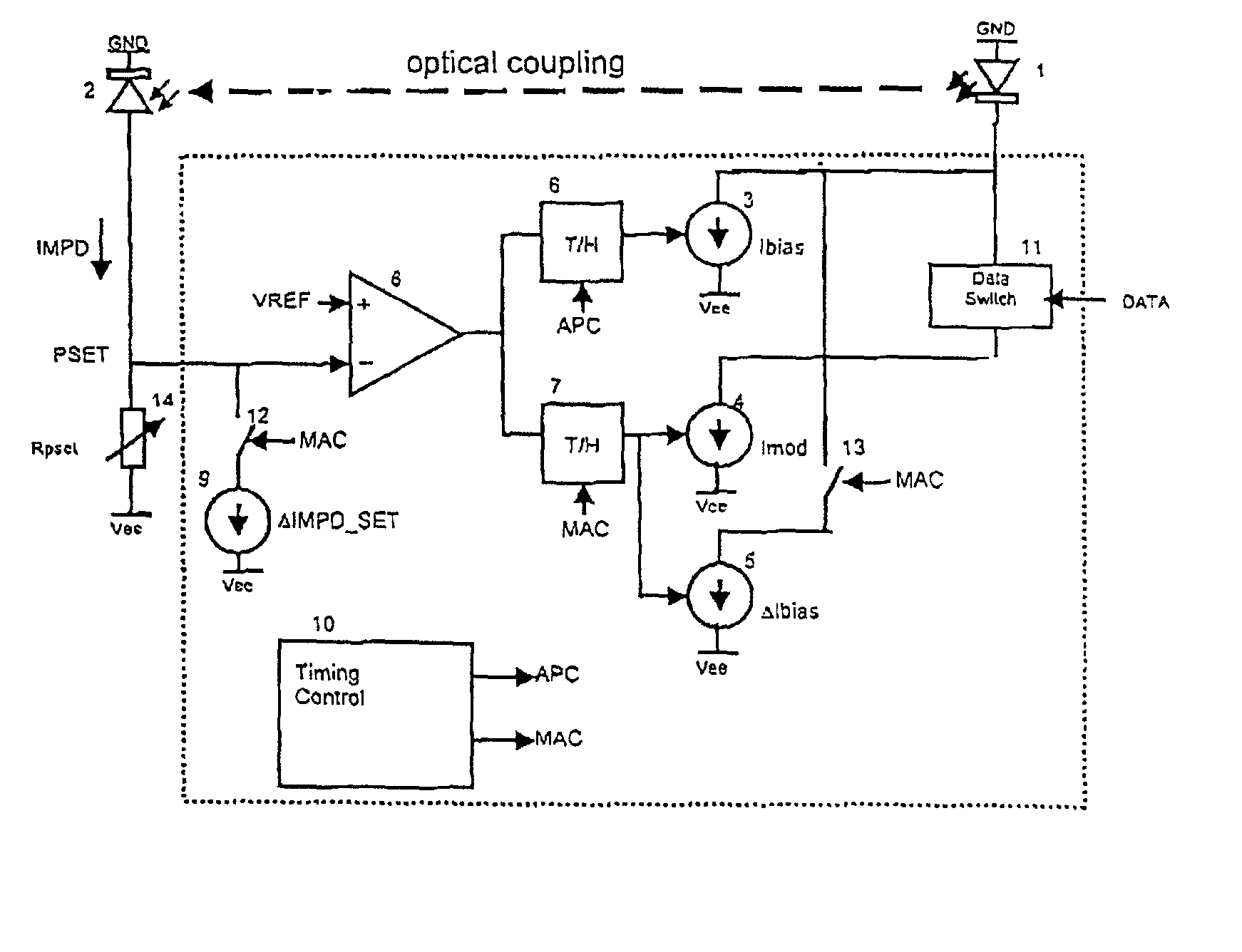
[0136] Referring to the drawings, and in particular to FIGS. 7.1 to 10, the present invention provides for a measurement of the OMA in the operating region of the power / current characteristic curve by effecting a measurement of the OMA at two positions on the curve and combining these two OMA measurements so as to effect an overall measurement value for the OMA that is adapted to take into account any variations in the slope arising from non-linearities in the operating region.

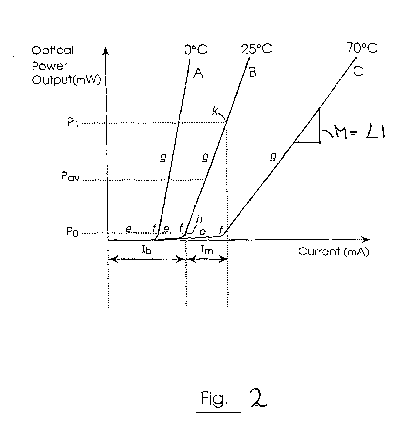
[0137] With reference to FIG. 7.1, we can define LI (LI being the average slope of the non linear laser characteristic curve in the operating region), as LI=(P.sub.1-P.sub.0) / Imod. It is possible to make a measurement of OMA by applying a test signals to the bias current Ibias and modulation current Imod so as to modulate the PI level with a waveform such as that shown in FIG. 7.1. This results in another optical level P.sub.1' being created, where P.sub.1'-P.sub.1=.DELTA.Imod*LI", where LI" is the slope of th...


PUM


Abstract

A method and circuit for measuring the optical modulation amplitude in the operating region of a laser diode is described. The method utilises two measurements of OMA, each measurement being related to the slope in a specific portion of the operating region of the power/current characteristic curve of the laser diode. By combining the two measurement values, the invention provides a 1 measurement for OMA in the operating region of the laser diode that allows for the presence of a non-linear response in the region.

Description

[0001] The invention relates to a method and to a control circuit for measuring the optical modulation amplitude (OMA) in the operating region of a laser diode. It also relates to a method and circuit for using the measured OMA as a control parameter in operation of the laser.BACKGROUND TO THE INVENTION[0002] Laser diodes are extensively used in optical transmission systems as light emitters for transmitting data in digital form over telecommunications networks. Optical transmission is based around generating a constant optical signal regardless of changes in the laser diode's operating environmental conditions or ageing considerations resultant from the progress of time.[0003] The transmission is achieved by analysis of the laser's optical power output / current input characteristic curve, which has an initial inactive linear portion which is almost horizontal with a very slight upward slope. The curve then has a knee portion which is generally called the threshold point at which sti...

Claims


Application Information

Patent Timeline
Patent Type & Authority Applications(United States)
IPC IPC(8): H01S5/00H01S5/062
CPCH01S5/06209H01S5/0014
Inventor MORLEY, SEANRUSSELL, BRIAN
Owner ANALOG DEVICES INC
Why Eureka
Try Eureka