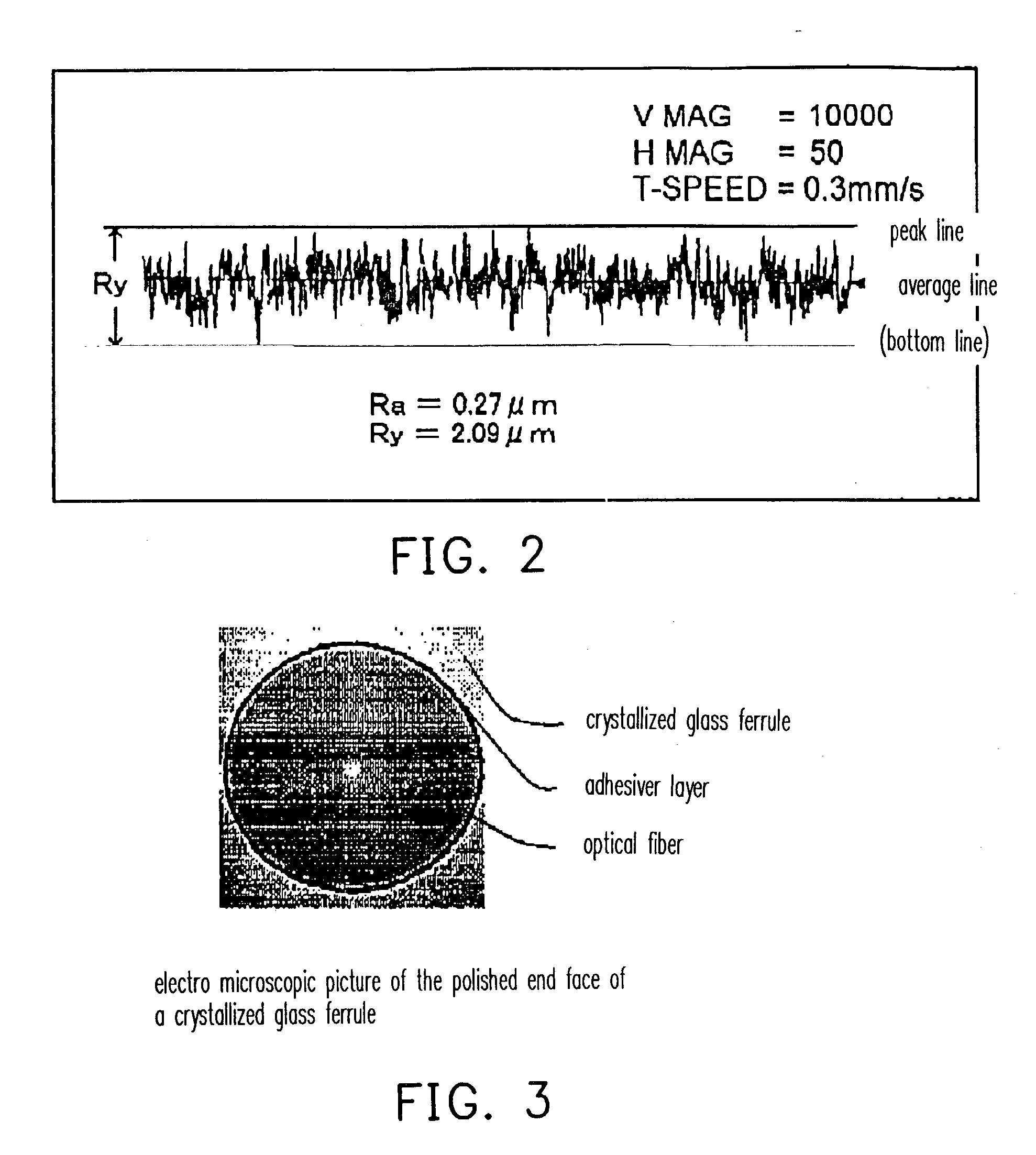
[0031] Since the capillary for optical fiber according to the present invention has the inner hole having the surface roughness Ra value of 0.1 .mu.m to 0.5 .mu.m, due to the affection of the peaks higher than the average line and dispersed on the inner hole surface, the
adhesive, including the
epoxy-type one with proper
viscosity, spreads uniformly in the circumferential direction to be retained on the surface of the inner hole in a stable manner, holding the optical fiber in the central position of the inner hole.
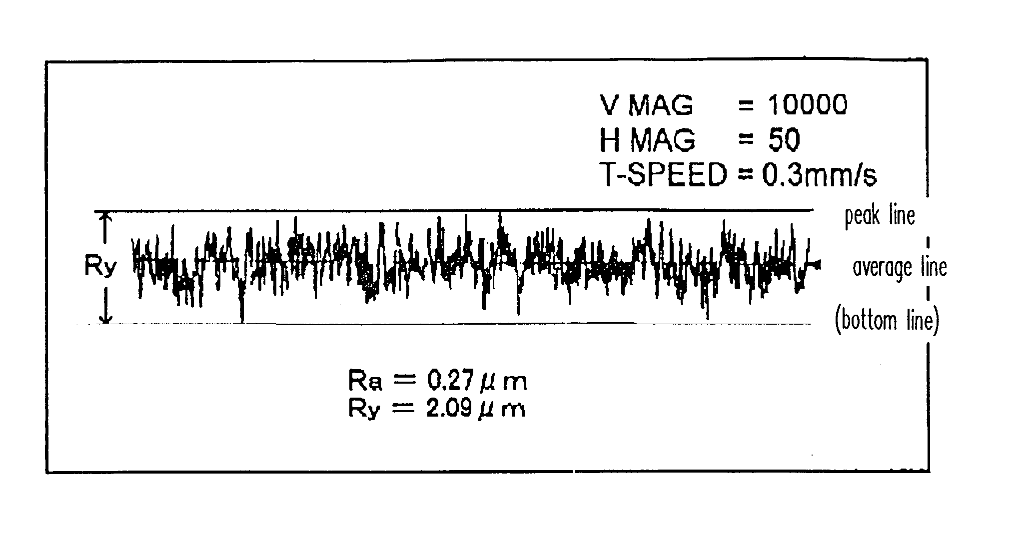
[0032] Also, the inner hole of the capillary for optical fiber of the present invention has the surface roughness Ry value of 4.0 .mu.m or less, which prevents the center of the maximum inscribed cylinder of the inner hole from decentered against the center of the circle determined by the average line of the surface roughness of the inner hole. This fact ensures that a high circularity of the inner hole and the concentricity between the inner hole and the outer periphery of the capillary are retained so that a desired core adjusting effect is obtained and the surface of inserted optical fiber is not damaged.
[0033] Further, in the capillary for optical fiber of the present invention, the difference between the average line and the peak line of the surface roughness in the inner hole is 2.0 .mu.m or less. Because of this fact, the center of the maximum inscribed cylinder of the inner hole is not decentered against the center of the circle determined by the average line of the surface roughness of the inner hole, even if the peaks and valleys of the surface roughness are not symmetrically with each other with respect to the average line of the surface roughness, so that the high circularity of the inner hole and the concentricity between the inner hole and the outer periphery of the capillary is secured and the surface of inserted optical fiber is not damaged. Thus, the desired core adjustment effect is obtained.
[0034] The capillary for optical fiber of the present invention is made of crystallized glass formed by precipitating crystals in amorphous glass. The crystallized glass is subjected to a heat treatment under a proper condition to precipitate crystallized grains on the surface of the inner hole, where the grains form the peaks. This process enables easy, effective manufacturing of the capillary having the inner hole with the surface roughness Ra value of 0.1 .mu.m to 0.5 .mu.m, the capillary having the inner hole with the surface roughness Ra value of 0.1 .mu.m to 0.5 .mu.m and Ry value of 4.0 .mu.m or less, the capillary having the inner hole with the surface roughness Ra value of 0.1 .mu.m to 0.5 .mu.m and the difference between the average line and the peak line of 2.0 .mu.m or less, and the capillary having the inner hole with the above surface roughness Ra and Ry values and the difference between the average line and the peak line of 2.0 .mu.m or less.
[0035] In the capillary for optical fiber of the present invention, the inner hole has a prescribed surface roughness formed by a mechanical process mean. Therefore, the inner hole with surface roughness Ra value of 0.1 .mu.m to 0.5 .mu.m, the capillary having the inner hole with the surface roughness Ra value of 0.1 .mu.m to 0.5 .mu.m and Ry value of 4.0 .mu.m or less, the capillary having the inner hole with the surface roughness Ra value of 0.1 .mu.m to 0.5 .mu.m and the difference between the average line and the peak line of 2.0 .mu.m or less, and the capillary having the inner hole with the above surface roughness Ra and Ry values and the difference between the average line and the peak line of 2.0 .mu.m or less, are manufactured under a
room temperature by using the internal
grinding (or
polishing)
machine and the like.
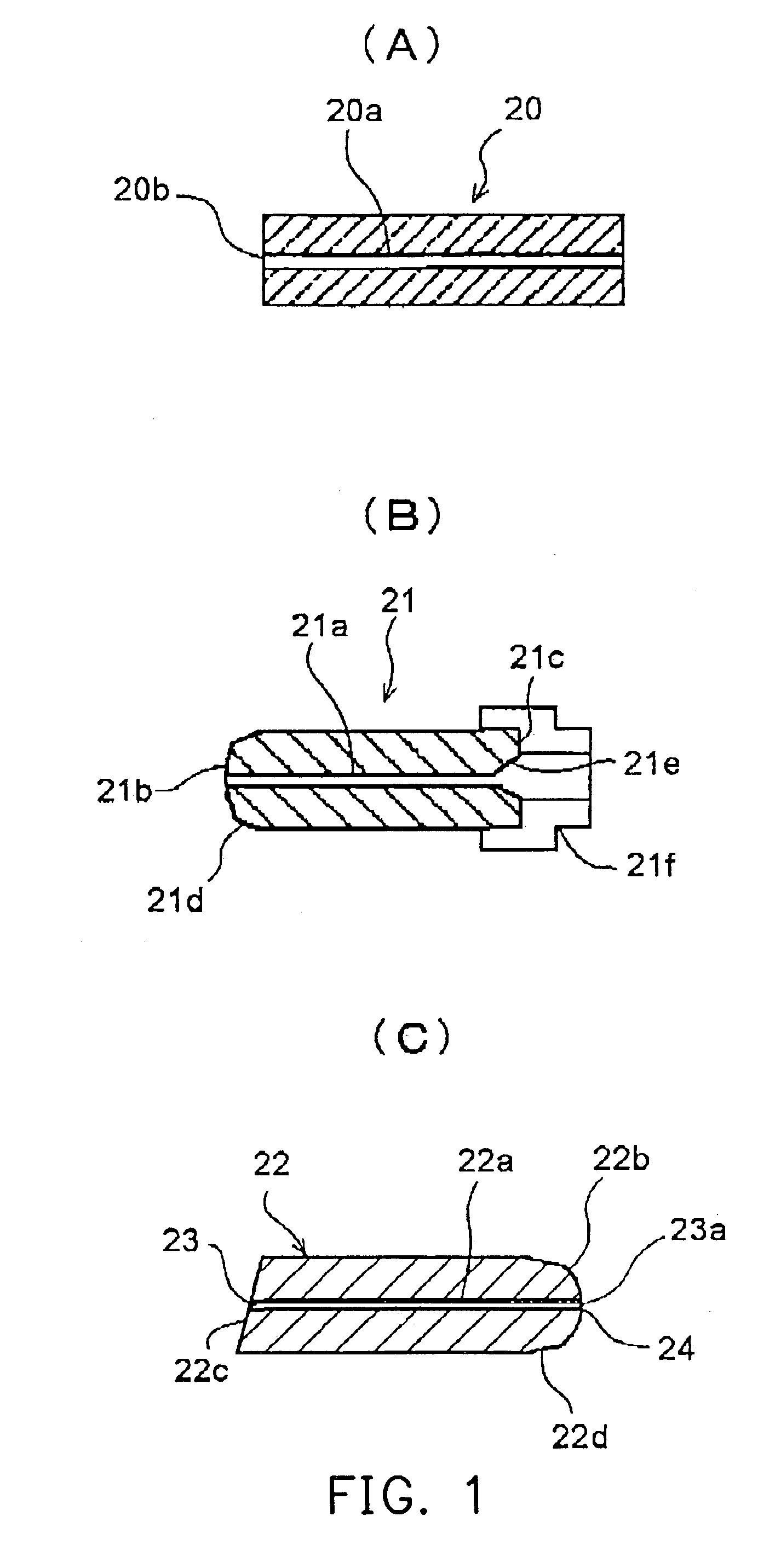
[0036] The ferrule for optical connector of the present invention is that the capillary for optical fiber as described above is formed with the chamfered part on one end thereof for guiding the ferrule into the sleeve and the flared part opened to the other end for guiding an optical fiber into the inner hole. Therefore, the optical fiber can be held precisely in the center of the inner hole of the ferrule for optical connector by the core adjusting effect produced by the above surface roughness of the inner hole of the invented capillary for optical fiber.
[0037] The optical-fiber-fixed capillary of the present invention comprises the capillary for optical fiber as described above and the optical fiber inserted and fixed into the inner hole of the capillary for optical fiber. Therefore, there is provided the optical-fiber-fixed capillary, in which the optical fiber is retained in the center of the inner hole by the core adjusting effect produced by the surface roughness of the inner hole.

