Autoexposure methodology in a digital camera

a digital camera and autoexposure technology, applied in the field of digital image processing, can solve the problems of underexposure, lack of details, overexposure of photographs,

Inactive Publication Date: 2003-05-29
RPX CORP
View PDF4 Cites 80 Cited by
  • Summary
  • Abstract
  • Description
  • Claims
  • Application Information

AI Technical Summary

Problems solved by technology

If too much light strikes the image sensor, the photograph will be overexposed.
Overexposure may result in a washed out and faded looking picture.
Too little light, on the other hand, produces an underexposed photograph that may be dark and lacking in details, especially in shadow areas.
Although most current digital cameras use a separate light sensor for automatic exposure control, there are drawbacks to this approach.
One drawback is cost.
Use of an external light sensor adds another component to the camera that increases the overall cost of manufacture of the camera.
In addition, a light sensor may also increase size of the camera and its power consumption.
Another problem is that existing autoexposure systems typically rely on the use of a flash device for lower light conditions.
However, use of a flash device also adds to the cost of manufacture of the camera as well as increasing its size and its power requirements.
One would think with present-day digital technology and scale, one could create a digital camera that is extremely small and portable, particularly since a digital camera is not constrained by the physical constraints of traditional photographic film.
This is not the case today, however.
As it turns out, the whole process of capturing light and generating a color digital image, such as with a digital camera, is a very compute-intensive process.
The upshot of this substantial processing requirement is that, paradoxically, digital cameras today are relatively bulky devices since they require relatively large batteries to support their processing needs.
Even with these large battery arrangements, digital cameras today have relatively short battery lives, such that the digital camera user is required to change out batteries at frequent intervals.
Perhaps the biggest drawback of such an approach, however, is the added bulk imparted to the camera itself with such a design.
And the smallest cameras today still remain film-based cameras, not digital ones, due in large part to the battery constraints of digital cameras.
Current autoexposure systems which rely on using only the main (e.g., CMOS) image sensor of a digital camera may, however, have problems in properly capturing an image in low light conditions without using a flash.
This longer exposure time may result in a blurred picture as the camera or the subject may move while the image is still being processed.
In low light settings the processing time required without flash may be impractical using current digital camera autoexposure methods.
A drawback to this approach is that these continual calculations may result in considerable power consumption, thereby requiring larger batteries and / or more frequent battery changes or recharging.
Another problem with current autoexposure systems is that these systems often rely on spot metering in which only a small area in the middle of the image is evaluated.
Spot metering may be problematic if, for instance, a dark object is located off center against a very light background.
In this instance, the dark object may not be exposed properly because it is not located in the area the meter is emphasizing.
Because only a portion of the scene is examined, other regions that are significantly lighter or darker may be underexposed when a spot metering technique is utilized.

Method used


Image

  • Autoexposure methodology in a digital camera
  • Autoexposure methodology in a digital camera
  • Autoexposure methodology in a digital camera

Examples


Embodiment Construction

[0033] The following description will focus on the currently-preferred embodiment of the present invention, which is implemented in a digital camera. The present invention is not, however, limited to any one particular application or any particular environment. Instead, those skilled in the art will find that the system and methods of the present invention may be advantageously employed on a variety of different devices. Therefore, the description of the exemplary embodiment that follows is for purpose of illustration and not limitation.

[0034] I. Digital Camera-based Implementation

[0035] A. Basic Components of Digital Camera

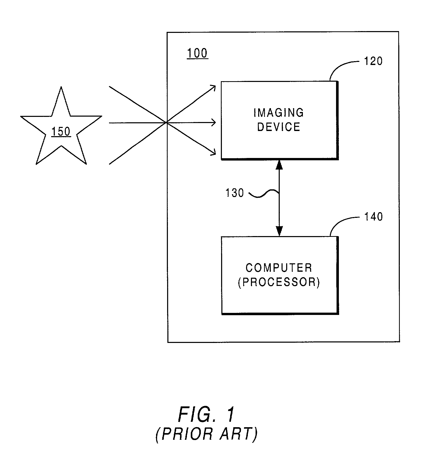
[0036] The present invention may be implemented on a media capturing and recording system, such as a digital camera. FIG. 1 is a very general block diagram of a digital camera 100 suitable for implementing the present invention. As shown, the digital camera 100 comprises an imaging device 120, a system bus 130, and a processor or computer 140 (e.g., microprocesso...


PUM


Abstract

An improved method for automatic exposure control at a digital camera is described. In response to a user request for capture of a digital image, image data is captured on the camera's image sensor. The captured image data includes pixel values of brightness of pixels of the image sensor. A histogram of pixel values is generated based upon brightness of pixels of the image sensor. The histogram that is generated is then evaluated to determine whether an image is overexposed or underexposed. Coarse exposure settings for capture of a digital image are automatically generated based upon scaling the histogram of pixel values towards the midpoint of a pre-selected interval. The coarse exposure settings and image data that have been captured are evaluated to determine whether light sources are present. In the event that light sources are determined not to be present, the coarse exposure settings are adjusted based upon not scaling said histogram beyond the largest histogram value.

Description

[0001] The present application is related to and claims the benefit of priority of the following commonly-owned provisional application(s): application serial No. 60 / 316,460 (Docket No. LS / 0030.00), filed Aug. 30, 2001, entitled "Improved Autoexposure Methodology in a Digital Camera", of which the present application is a non-provisional application thereof. The disclosure of the foregoing application is hereby incorporated by reference in its entirety, including any appendices or attachments thereof, for all purposes.COMPUTER PROGRAM LISTING APPENDIX[0002] A Computer Program Listing Appendix, containing six (6) total files on compact disc, is included with this application.Copyright Notice[0003] A portion of the disclosure of this patent document contains material that is subject to copyright protection. The copyright owner has no objection to the facsimile reproduction by anyone of the patent document or the patent disclosure as it appears in the Patent and Trademark Office patent...

Claims


Application Information

Patent Timeline
Patent Type & Authority Applications(United States)
IPC IPC(8): G03B3/00H04N5/235
CPCG03B3/00H04N5/2354H04N5/2352H04N5/2351H04N23/72H04N23/71H04N23/74
Inventor EASWAR, VENKAT
Owner RPX CORP
Why Eureka
Try Eureka