Method for surface corona/ozone making, devices utilizing the same and methods for corona and ozone applications

Inactive Publication Date: 2003-06-12
ANDREEV SERGEY I +1
View PDF4 Cites 100 Cited by
  • Summary
  • Abstract
  • Description
  • Claims
  • Application Information

AI Technical Summary

Problems solved by technology

Various apparatus and methods have been proposed for corona/ozone making, but all of them have several serious flaws.
First, they all operate at a very high and therefore dangerous voltage that result in large, bulky and heavy generating apparatus.
Second, the flowing of oxygen containing gas (air or oxygen) through the corona discharge and treating camera is required.
Gas blowing system stipulates complicate treating equipment and in addition to being costly.
Third, ozone output for existing devices is small if it calculated as a ratio of ozone output to ozonizer size or weight.
The wire radius R has a low limit, because electrical field strength is inversely proportional to the wire radius R and smaller radius leads to the increase strength in the dielectric and this way increase the probability of the dielectric breakdown.
Only corona, which takes place in front of developing sparks produces ozone with very small concentration and minimal efficiency

Method used


Image

  • Method for surface corona/ozone making, devices utilizing the same and methods for corona and ozone applications
  • Method for surface corona/ozone making, devices utilizing the same and methods for corona and ozone applications
  • Method for surface corona/ozone making, devices utilizing the same and methods for corona and ozone applications

Examples


Embodiment Construction

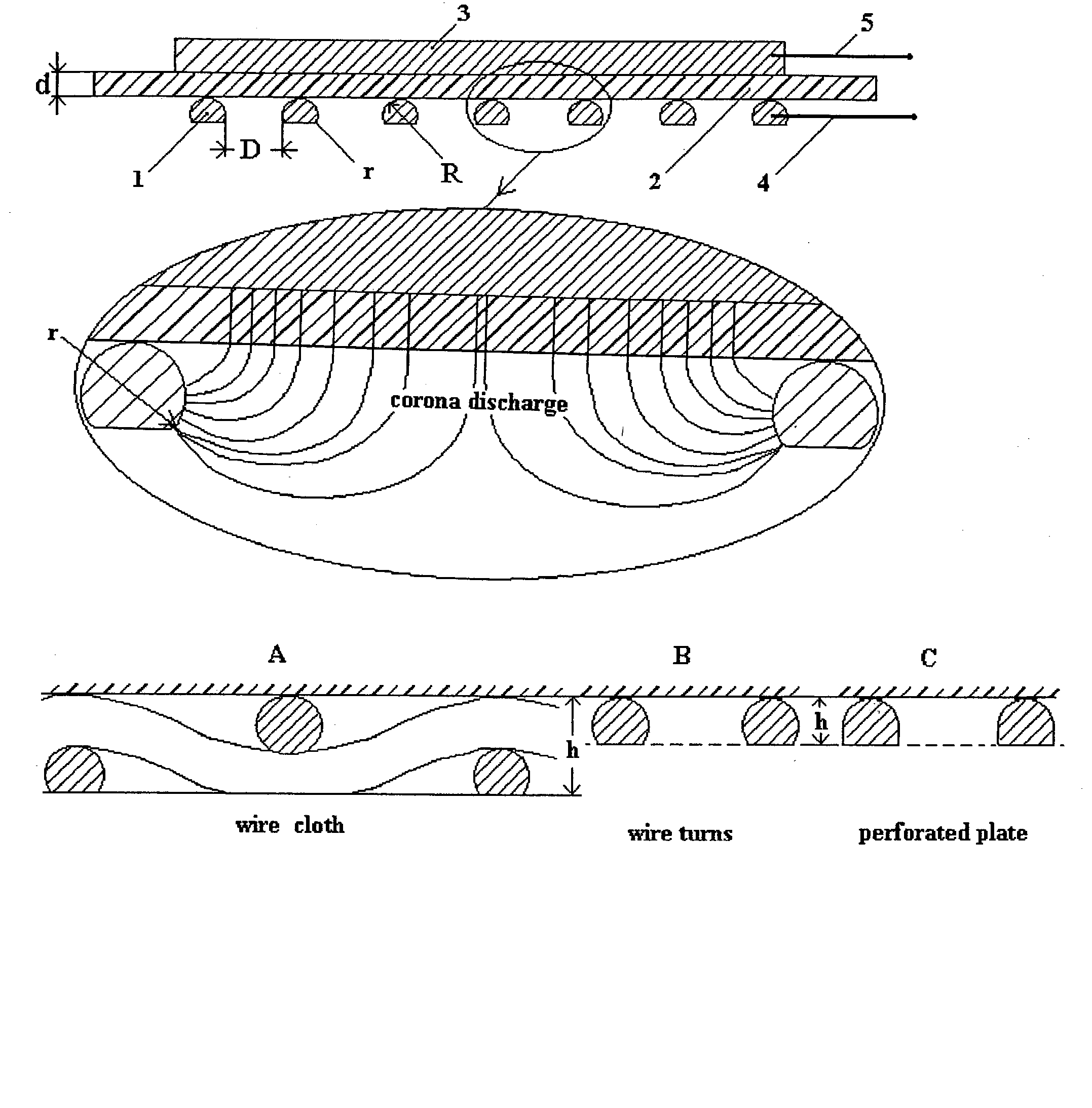
[0103] FIG. 1 is a cross section view of the corona / ozone-generating element with the claimed sizes. The streamlines of the electrical field or corona current are shown. Corona discharge has a larger intensity where said streamlines have larger density. When the sine voltage rises, corona discharge disperses inside of holes D in the net electrode 1 on a dielectric spacer / film 2. Said dielectric is placed between said net electrode 1 and rigid base electrode 3. AC voltage is applied by connectors 4 and 5 to the net electrode 1 and to the base electrode 3 correspondingly. The high voltage capacitor technology is used for creating said ozone-generating element. According to this technology it is necessary to have a tight contact between said dielectric spacer / film 2 and the base electrode 3 and said dielectric spacer / film must have a higher capacity and high enough breakdown voltage at the same time. The corona discharge is located in series with said dielectric capacity and the capaci...


PUM


Abstract

A method for making surface corona discharge, which produces ozone gas and apparatus for producing the same are disclosed, in which a dielectric spacer/film having a specific capacity C' equal to or more than 200 nanofarad per square meter positioned between the base electrode and the net electrode. Said net electrode is a wire net or a perforated metal or a wire winding having an open area not less than about 70%, and a size of hole D equals to or less than about 0.7V/P, where V is a voltage in kilovolts and P is pressure of an ambient air or an oxygen in atmospheres. Net electrode has radius R of wire or radius of an edge of openings in the perforated metal equal to or more than about 1.6d, where d is the thickness of the said dielectric spacer/film, which is determined by a fundamental formula d=9k/C', where d is in millimeters, C' is in nF/m2, and k is dimensionless dielectric constant k of given material. Under disclosed parameters said surface corona is safe for human contact if said net electrode is grounded. Start voltage Vst of ozone production is determined by experimental formula Vst=0.7+60/C', kV, here C' in nF/m2. The even and high intensity corona surface and high ozone output takes place if the operating voltage is more than about 3Vst. AC power supply is applied to produce ozone gas at "home" voltage 0.7-1.0 kV and produces ozone gas more effectively at 2,5-3.6 kV. A method for disinfection and decontamination of objects by using the direct corona contact and apparatus for making the same is disclosed, in which safe corona surface is placed on said object and is acting by ozone, ultraviolet and ion bombing simultaneously in the unique environment, which takes place inside of the safe corona. A method for ozone disinfection and decontamination and devices for making the same is disclosed, in which said ozone generating element is placed in a closed container/room with or without treated objects and produce a high ozone concentration due to effective ozone dispersion from corona surface without blowing of air/oxygen through said container/room.

Description

[0001] This patent is based on the provisional Patent Application No. 60 / 339,190, filed Dec. 11, 2001.REFERENCES CITED[0002]1 U.S. PATENT DOCUMENTS 4,614,573 September 1986 Masuda et at. 204 / 176; 4,666,679 May 1987 Masuda et al. 422 / 186.2 5,364,600 November 1994 Stiehl et al. 422 / 186.07 5,147,678 Sep. 15, 1992 Foerch et al. 427 / 40 5,292,479 Mar. 08, 1994 Harada et a. 422 / 005 5,429,743 Feb. 27, 1996 Schneider et al. 8 / 149.2 5,868,999 Feb. 09, 1999 Karison et al. 422 / 030 6086833 Jun. 11, 2000 Conners, et al. 422 / 292 4549477 Oct. 29, 1985 McCabe, Jr. 99 / 477 6,007,770 December 1999 Peiper et al 422 / 22 5,501,844 Mar. 26, 1996 Kasting et al. 422 / 186.15 1,796,110 Mar. 10, 1931 F. Lechler. 6,080,531 Jun. 27, 2000 Carter et al. 430 / 329 6,115,862 Sep. 12, 2000 Cooper et al. 8 / 158 4019986 April 1977 Burris et al. 210 / 139 5,430,228 Jul. 04, 1995 Ciambrone et al. 588 / 200[0003]2 FOREIGN PATENT DOCUMENTS 2,024,427 Dec. 15, 1994 Andreev Russian Patent Off. 08,238,323 February 1998 Kozo Japan Patent...

Claims


Application Information

Patent Timeline
IPC IPC(8): A23L3/3409A61L2/00A61L2/14A61L2/20A61L9/015A61L9/22B01D53/32C01B13/11C02F1/78E03D9/00
CPCA23L3/3409A23V2002/00E03D9/005C02F2201/782A61L2/0011A61L2/0094A61L2/14A61L2/202A61L9/015A61L9/22A61L2202/11B01D53/32C01B13/11C01B2201/12C01B2201/22C01B2201/32C01B2201/34C01B2201/82C02F1/78A23V2200/10A23V2250/128
Inventor ANDREEV, SERGEY I.ANDREEV, IVAN S.
Owner ANDREEV SERGEY I
Why Eureka
Try Eureka