
Method of servicing a pen when mounted in a printing device

a printing device and pen body technology, applied in printing, other printing devices, etc., can solve the problems of affecting the quality of output, the orifice plate of the printhead, and the accumulation of excess dried ink around the printhead,

Inactive Publication Date: 2003-06-26
HEWLETT PACKARD DEV CO LP
View PDF0 Cites 69 Cited by
  • Summary
  • Abstract
  • Description
  • Claims
  • Application Information

AI Technical Summary

Benefits of technology

[0014] By executing the servicing process only when it appears as necessary helps to improve the productivity of the printer and to reduce the waste of ink and to wear the nozzle plate.
[0018] Thus, it is provided a simple way of storing and comparing nozzle health information.
[0020] This helps to avoid to run the servicing process when only few nozzles are detected as malfunctioning.
[0027] Specific methods according to the present invention, recognize that by using a history of the nozzle health it is possible to improve the quality of the output in a number of different ways.

Problems solved by technology

The orifice plate of the printhead, tends to pick up contaminants, such as paper dust, and the like, during the printing process.
In addition, excess dried ink can accumulate around the printhead.
The accumulation of either ink or other contaminants can impair the quality of the output by interfering with the proper application of ink to the printing medium.
If ink accumulates on the orifice plate, mixing of different coloured inks (cross-contamination) can result during use.
If colours are mixed on the orifice plate, the quality of the resulting printed product can be affected.
Furthermore, the nozzles of an ink-jet printer can clog, particularly if the pens are left uncapped in an office environment.
Living longer and firing more drops of ink means that there are greater probability that the printer print quality degrade and / or deviate along life.
One big drawback of this system when implemented, e.g. as in DesignJet .COPYRGT.
This usually leads to either an unacceptable loss of throughput and printer productivity (because the printer stops and waits for an answer, the automatic recovery process is very time consuming, and causes a big waste of ink particularly when running the priming functions) or to excessive printhead replace or continue messages that users disable nozzle check via front panel, causing throughput losses.

Method used


Image

  • Method of servicing a pen when mounted in a printing device
  • Method of servicing a pen when mounted in a printing device
  • Method of servicing a pen when mounted in a printing device

Examples


first embodiment

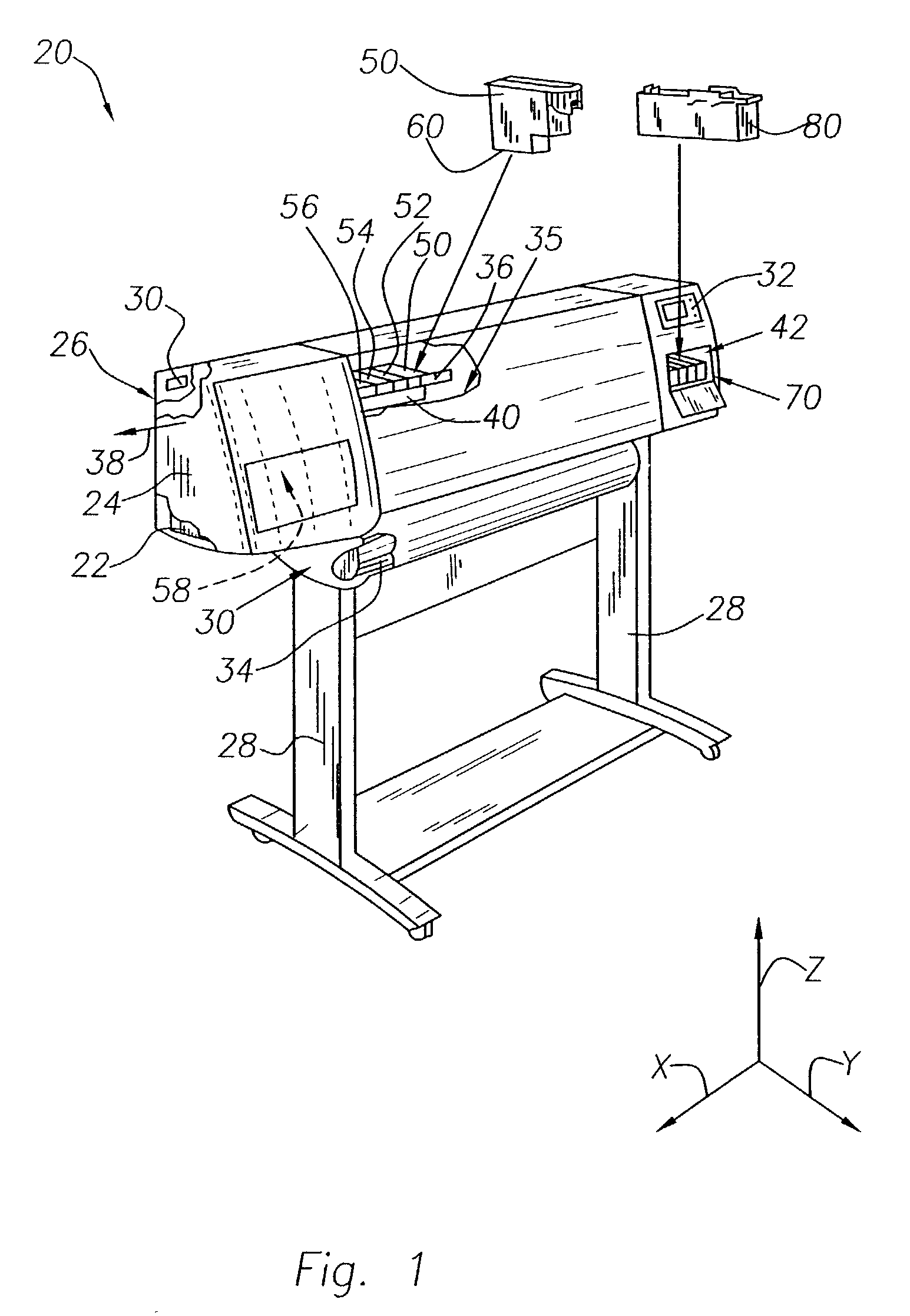
[0049] FIG. 1 illustrates an inkjet printing mechanism, here shown as an inkjet printer 20, constructed in accordance with the present invention, which may be used for printing conventional engineering and architectural drawings, as well as high quality poster-sized images, and the like, in an industrial, office, home or other environment. A variety of inkjet printing mechanisms are commercially available. For instance, some of the printing mechanisms that may embody the present invention include desk top printers, portable printing units, copiers, cameras, video printers, and facsimile machines, to name a few. For convenience the concepts of the present invention are illustrated in the environment of an inkjet printer 20.

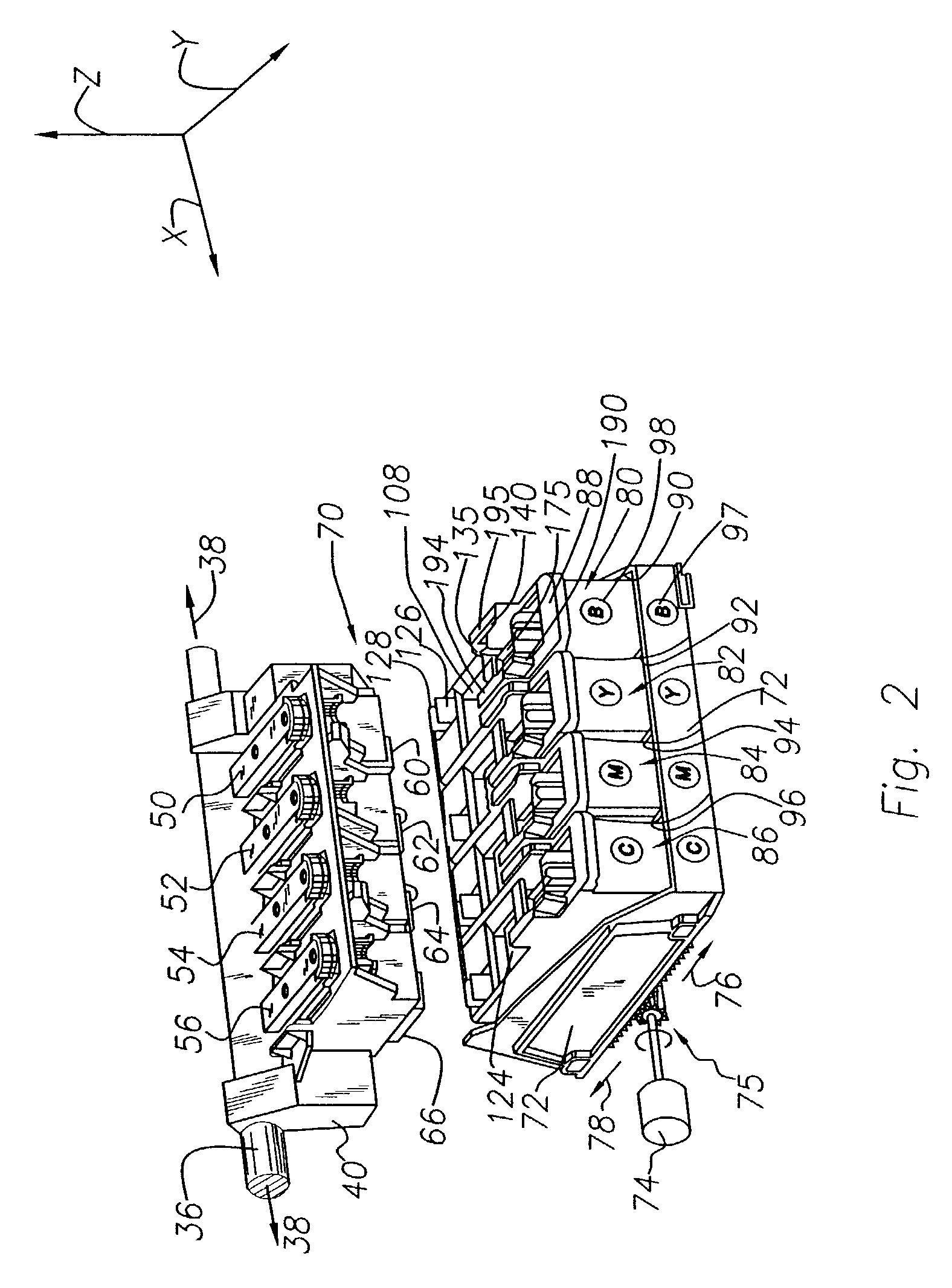
[0050] While it is apparent that the printer components may vary from model to model, the typical inkjet printer 20 includes a chassis 22 surrounded by a housing or casing enclosure 24, typically of a plastic material, together forming a print assembly portion 26 o...

embodiment 50

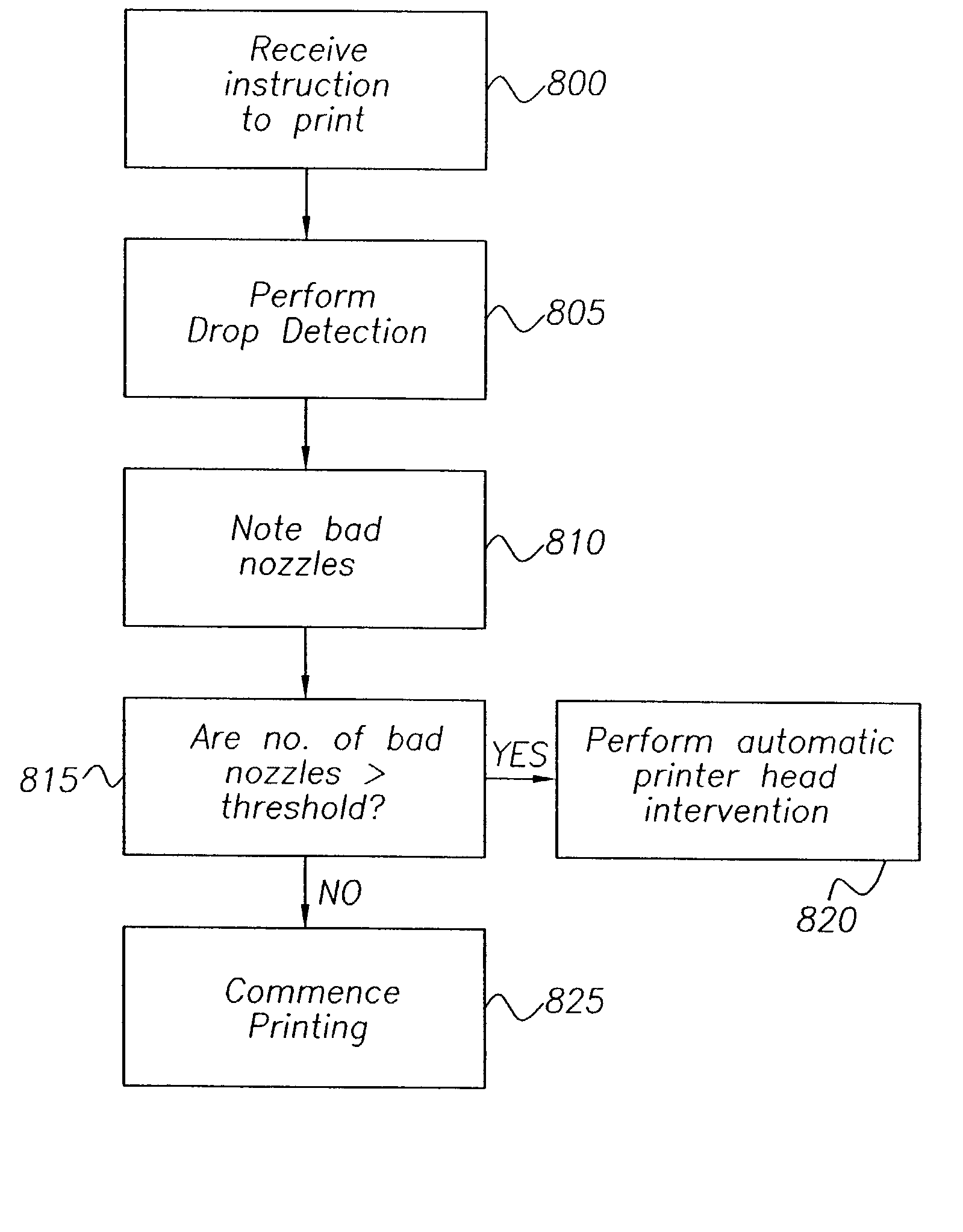
[0121] The process start at step 1100 when the signal to start printing a plot is sent to the printer 20. At this stage a lightweight servicing step 1180 is executed. A lightweight servicing may include conventionally spitting a predetermined number of droplets into the spittoon 108. According to the time the pen rested in the service station capped, an higher predetermined number of droplets may be spitted and a conventional wiping step can be also added. At step 1110 a drop detection process is performed, as described previously described, on the printhead 400. At test 1120 it is verified if the number of nozzles out of the nth percentile, in this embodiment 50, of the drop detection history is below a predetermined Recovery threshold value, here 2 if the printhead pertains to the black pen or 6 if the printhead pertains to the for color pens, or the last drop detection has revealed a current number of nozzles out is smaller than a predetermined End of Life threshold value, here e...

second embodiment

[0194] In accordance to the invention, the end of life of a printhead is reached when DDnth value will be at least equal or bigger than the End of Life Threshold which in this embodiment is 5 for a black printhead and 8 for a color printhead.

[0195] After some tests the Applicant has observed that the result of a single drop detection step may not provide a real picture of the trend on the functionality of a pen. FIG. 16 shows how may vary the numbers of nozzles out detected, reporting each drop detection measured, based on the usage of the pen (number of drops fired). In FIG. 17 it is shown how considering DD3rd as the number of nozzle out detected for each drop detection provides a clearer picture of the variation of the capabilities of the pen. It should also be noted that DD3rd is increasing and approaching the End of Live Threshold after about 50 million drops per nozzle. The skilled in the art should appreciate how, according to FIG. 16, the first time that the actual number of...


PUM


Abstract

A method of servicing a pen comprising a printhead, having a plurality of nozzles, mounted in an inkjet printing device, comprising a servicing area and a drop detector comprising the following steps performing a drop detection on the printhead to check if any of the nozzles of the printhead are malfunctioning; storing the result of the more recent drop detection operation, together with the results of the previous drop detections to keep a history of the health status of each nozzle; deciding whether or not to execute a recovery service in the servicing area to attempt to recover the current malfunctioning nozzles, based on the more recent status of the nozzles and on the history of the health status of the nozzles.

Description

[0001] The present invention relates to inkjet printing devices, and particularly although not exclusively to a method and apparatus for servicing a pen when mounted in a printing device.BACKGROUND TO THE INVENTION[0002] Inkjet printing mechanisms may be used in a variety of different printing devices, such as plotters, facsimile machines and inkjet printers, collectively called in the following as printers, to print images using a colorant, referred to generally herein as "ink." These inkjet printing mechanisms use inkjet cartridges, often called "pens," to shoot drops of ink onto a page or sheet of print media. Some inkjet print mechanisms carry an ink cartridge with an entire supply of ink back and forth across the sheet. Other inikjet print mechanisms, known as "off-axis" systems, propel only a small ink supply with the printhead carriage across the printzone, and store the main ink supply in a stationary reservoir, which is located "off-axis" from the path of printhead travel. ...

Claims


Application Information

Patent Timeline
Patent Type & Authority Applications(United States)
IPC IPC(8): B41J2/01B41J2/125B41J2/165B41J2/18B41J2/185
CPCB41J2/16579
Inventor BRUCH, XAVIERGIRONES, XAVIERMURCIA, ANTONITAYLOR, CHRISTOPHERVEGA, RAMON
Owner HEWLETT PACKARD DEV CO LP
Learn More