Optical information recording medium

a technology of optical information and recording medium, which is applied in the field of optical information recording medium, can solve the problems of dyes having a drawback, dyes cannot have good recording/reproducing characteristics, and complex index of refraction has a large wavelength dependency

Inactive Publication Date: 2003-07-03
RICOH KK
View PDF28 Cites 12 Cited by
  • Summary
  • Abstract
  • Description
  • Claims
  • Application Information

AI Technical Summary

Benefits of technology

[0028] Accordingly, an object of the present invention is to provide an optical information recording medium which can be used as a DVD-R or a DVD+R and which has good recording characteristics with a small wavelength dependency.
[0002] The present invention relates to an optical information recording medium, and more particularly to an information recording medium including a light absorbing recording layer including a dye.
[0069] (3) having a function of improving the photo-stability of a dye to be included together with the formazan chelate compound.
[0045] FIG. 5 is a graph illustrating the light absorption spectra of the optical information recording media of Example 1 and Comparative Example 1 at a wavelength range of from 645 to 670 nm; and

Problems solved by technology

However, dyes have a drawback in that the complex index of refraction has a large wavelength dependency.
The light absorption of the dyes mentioned above for use in the conventional CD-Rs, such as pentamethine cyanine dyes and phthalocyanine dyes, have so large wavelength dependency that the dyes cannot have good recording / reproducing characteristics (i.e., information cannot be recorded and reproduced) when laser light having a wavelength of 650 nm is used for information recording and reproducing.
These dyes have good optical characteristics at the wavelength of 650 nm, but do not have good optical characteristics against light having a wavelength in a range of from 645 to 670 nm, which light is typically used for DVD+R drives.
Namely, when the wavelength of the laser light emitted by a DVD drive changes due to changes of the driving conditions such as environmental conditions, a problem in that information cannot be recorded in the recording medium tends to occur.
In particular, since the wavelength of laser light emitted by a light source tends to shift in the long wavelength direction under high temperature conditions, the absorption coefficient k decreases and thereby the recording sensitivity of the recording medium deteriorates.
However, the application does not pay attention to the wavelength (i.e., 645 to 670 nm) of the light emitted by DVD drives, and therefore the wavelength dependency of the recording sensitivity cannot be improved.
Such high density recording, i.e., to record a pit much smaller than that for CDs, cannot be achieved by only adjusting the optical characteristics, and it is needed to adjust the heat decomposition properties of the dyes used.
In addition, it is needed to solve a problem in that the jitter of recorded signals is large.
When the thermal decomposition temperature is higher than 400.degree. C., the power of the laser source has to be increased and in addition the recorded pits tend to have a large jitter.
When the difference between the thermal decomposition temperatures of the dye compounds is greater than 100.degree. C., pits having a good form cannot be prepared, resulting in increase of jitter of the recorded pits.
When the thermal decomposition temperature is lower than 120.degree. C., the durability of the resultant recording medium deteriorates particularly when used under high temperature conditions.
In addition, the recording medium tends to be thermally damaged during the manufacturing processes, resulting in deterioration of productivity of the recording medium.
When the carbon number is too large, the absorption of the recording layer per unit film thickness decreases, and thereby proper complex index of refraction cannot be imparted to the recording layer.
In addition, when the width is too wide, the reproduced signals are largely affected by interference between a groove and the adjacent groove, and thereby the amplitude of the wobble signals largely is varied.
As a result thereof, precision in reading track signals deteriorates, and the jitter increases.

Method used


Image

  • Optical information recording medium
  • Optical information recording medium
  • Optical information recording medium

Examples


example 1

[0173] The following components were dissolved in 2,2,3,3-tetrafluoropropa-nol to prepare a dye solution (i.e., a recording layer coating liquid).

[0174] Dye Compound (.alpha.)

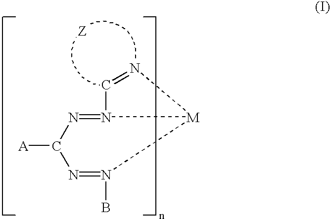
[0175] Formazan Ni Chelate Compound (1)

[0176] having formula (I) 49 moles 7

[0177] (Z: 3,6-phenoxytriazole, A: 2-trifluoromethylphenyl, B: phenyl, M: Ni, n=2)

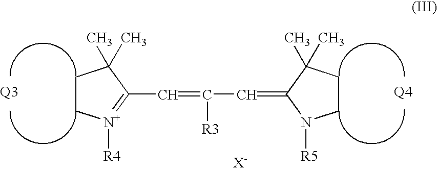
[0178] Trimethinecyanine Dye (2)

[0179] having fromula (III) 49 moles 8

[0180] (Q3 and Q4: a group forming a benzoindolenine ring together with a pyrrole ring, R3: --H, R4 and R5: --CH.sub.3, X.sup.-: --ClO.sub.4.sup.-)

[0181] Dye Compound (.beta.)

[0182] Pentamethinecyanine Compound (11)

[0183] having formula (VI) 2 moles 9

[0184] (Q3 and Q4: a group forming a benzoindolenine ring together with a pyrrole ring, R3: --H, R4 and R5: --CH.sub.3, X.sup.-: --ClO.sub.4.sup.-)

[0185] The recording layer coating liquid was coated by a spin coating on a polycarbonate disc having a diameter of 120 mm and a thickness of 0.6 mm, on which a guide groove having a depth of about...

example 2

[0197] The procedures for preparation and evaluation of the recording medium in Example 1 were repeated except that the dye compounds (.alpha.) and (.beta.) were replaced with the following dyes, respectively, and the solvent was replaced with a mixture solvent of tetrahydrofuran, 2-ethoxyethanol and ethylcyclohexanone.

[0198] Dye Compound (.alpha.)

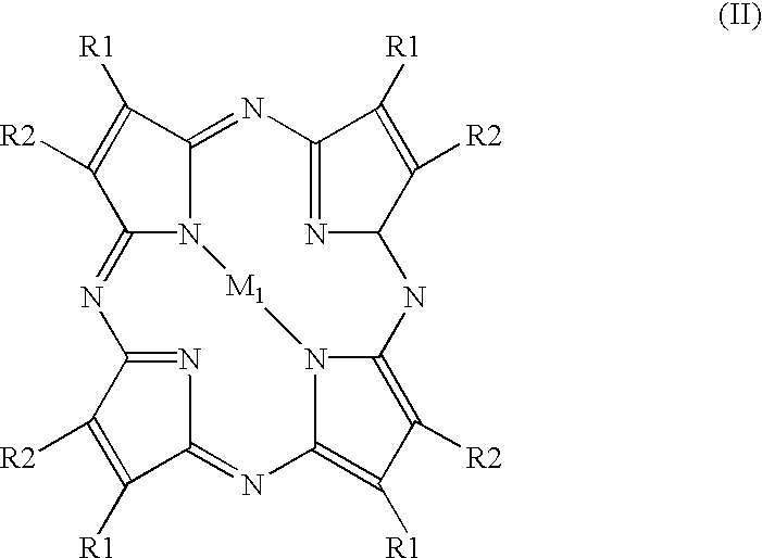
[0199] Tetraazaporphyradine Compound (3)

[0200] having formula (II) 90 moles 10

[0201] (M1: Cu, R1: --O--C(CF.sub.3).sub.2--C.sub.5H.sub.6, R2: --H)

[0202] Dye Compound (.beta.)

[0203] Phthalocyanine Compound (12)

[0204] having formula (V) 10 moles 11

[0205] (M2: VO; A1, A3, A5, A7: --O--O--C(CF.sub.3).sub.2--C.sub.5H.sub.6-;

[0206] A2, A4, A6, A8: --H)

[0207] Thus, an optical information recording medium was prepared.

[0208] The evaluation results are shown in Table 2. As can be understood from Table 2, the recording medium of Example 2 has good recording sensitivity.

example 3

[0209] The procedures for preparation and evaluation of the recording medium in Example 1 were repeated except that the Pentamethinecyanine compound (11) was replaced with a dye compound (13) having formula (V), and the molar ratio of the compounds (1), (2) and (13) was changed to 46:46:8. 12

[0210] (M2: Si(OCOC.sub.4H.sub.9).sub.2; A1, A3, A5, A7: --O--CH.sub.2--CF.sub.2--CF.sub.2--CF.sub.3; A2, A4, A6, A8: --H)

[0211] The evaluation results are shown in Table 2. As can be understood from Table 2, the recording medium of Example 3 has good recording sensitivity.


PUM

PropertyMeasurementUnit
wavelength rangeaaaaaaaaaa
molar ratioaaaaaaaaaa
thermal decomposition temperatures Tαaaaaaaaaaa

Abstract

An optical information recording medium including a substrate in which at least one of a groove and a pit is formed; a recording layer located overlying the substrate and including a dye; and a reflection layer located overlying the recording layer, wherein the optical information recording medium has an absorbance curve with an absorbance L of from 10 to 40% against light having a wavelength lambd of from 645 nm to 670 nm, a ratio (Lmax / Lmin) of a maximum absorbance Lmax of the absorbance curve to a minimum absorbance Lmin of from 1.0 to 2.0 at the wavelength range of from 645 nm to 670 nm, and a reflectance of from 45 to 85% against the light having a wavelength lambd of from 645 nm to 670 nm.

Description

[0001] 1. Field of the Invention[0002] The present invention relates to an optical information recording medium, and more particularly to an information recording medium including a light absorbing recording layer including a dye.[0003] 2. DISCUSSION OF THE RELATED ART[0004] Recently, recordable compact discs such as CD-Rs and CD-RWs have been developed for commercial operation, and are widely used as well as read only compact discs (CDs).[0005] Information can be additionally recorded in CD-Rs and CD-RWs whereas information cannot be recorded in CDs. The information signals recorded in CD-Rs and CD-RWs fulfill the specifications of conventional CDs and therefore the recorded information can be reproduced by marketed CD players.[0006] Published Japanese Patent Application No. 2-42652 discloses a CD-R which is prepared by spin-coating a dye on a substrate to form a light absorbing recording layer thereon and then forming a metal reflection layer on the recording layer. Dyes are typic...

Claims


Application Information

Patent Timeline
Patent Type & Authority Applications(United States)
IPC IPC(8): G11B7/0045G11B7/007G11B7/24076G11B7/24079G11B7/248
CPCG11B7/24076G11B7/248G11B7/24079Y10S430/146
Inventor YASHIRO, TOHRUNOGUCHI, SOHTOMURA, TATSUYA
Owner RICOH KK
Why Eureka
Try Eureka