[0010] By contrast, the
single injection orifice plate whose dome-shaped convexity is oriented upstream is advantageous in the fuel injector according to the present invention. Due to this measure, the fuel jets may be arranged on the lateral surface of a double cone. Despite a large apex angle, the fuel mixture does not become leaner in the area of the fuel injector's central axis. The focus of the discharged fuel is in the
combustion chamber rather than in the fuel injector.
[0011] A further
advantage is the large available surface compared with U.S. Pat. No. 5,484,108, which allows a larger number of discharge orifices to be arranged in the dome-shaped convexity without the widths of the webs between the discharge orifices becoming so narrow that
mechanical stability is critically reduced. The discharge orifices may be arranged along a spiral whose radial dimension is significantly enlarged.
[0012] In contrast to the single-piece design of the fuel injector known from German Patent Application 198 27 219 A1, the fuel injector according to the present invention has the
advantage that the material of the spray-orifice disk undergoes reinforcement in the molding process, for example, via cold molding. This allows thinner materials to be used for the spray-orifice disk, which in turn simplifies the introduction of discharge orifices and the fastening of the spray-orifice disk to the fuel injector. Manufacturing costs are reduced.
[0013] In addition, variants are simply formed in an advantageous manner. Both fuel metering and the discharge pattern are adjustable by installing a different spray-orifice disk. This allows cost effective adjustments to
customer requirements, while using mostly identical parts.
[0014] It is furthermore advantageous that, when off-dimension discharge orifices are detected, only an inexpensive punch-bent part is rejected. The housing body, which is considerably more expensive to manufacture, may continue to be used.
[0015] Advantageous refinements of the fuel injector according to the present invention are possible through the measures recited in the subclaims.
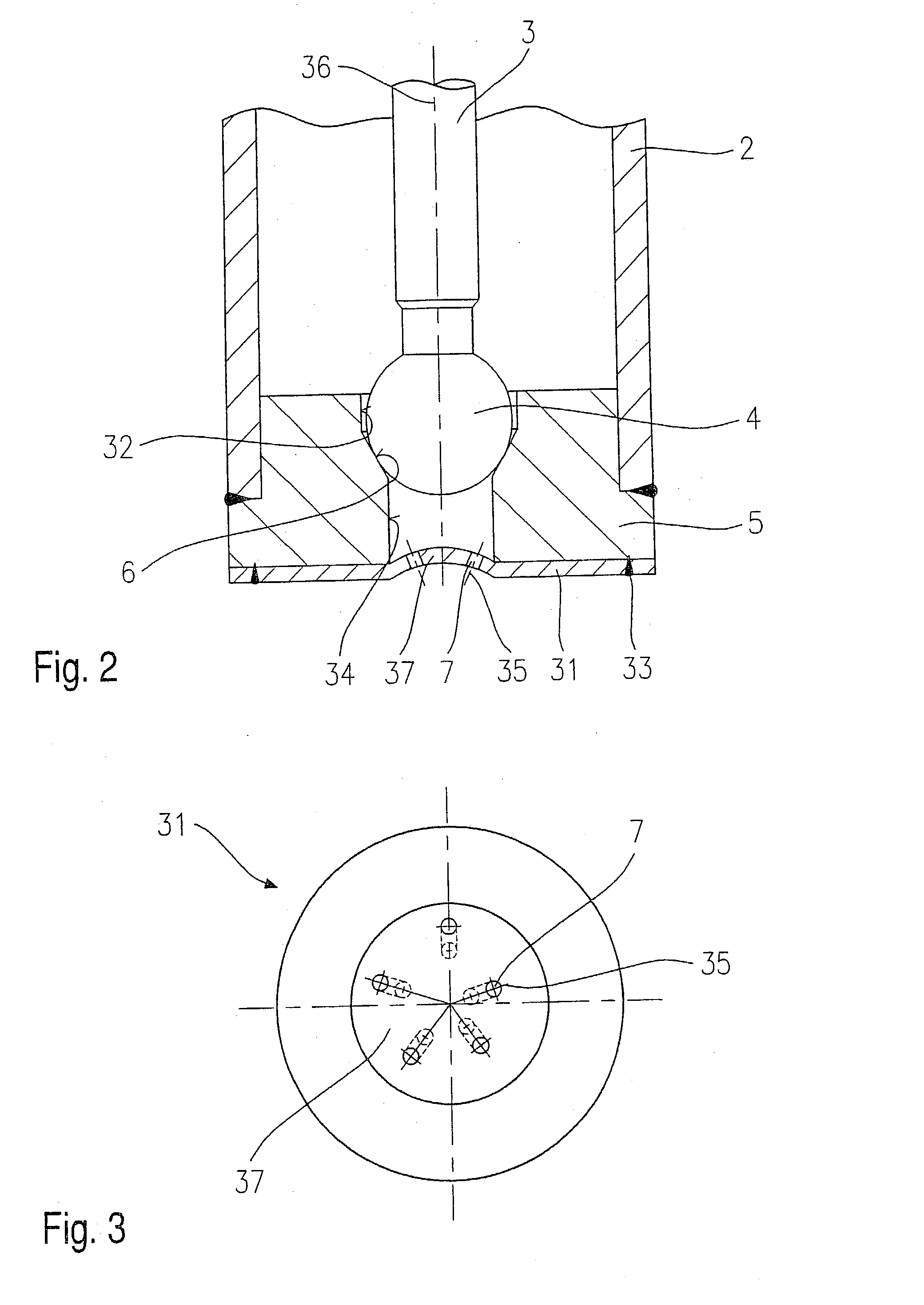
[0016] For example, by arranging the discharge orifices along a spiral, the fuel is dischargeable asymmetrically in a controlled manner. The individual fuel jets do not collide, since the discharge orifices are arranged so that each fuel jet passes between two fuel jets of the opposite discharge orifices. Particularly advantageous in the case of an asymmetrical discharge pattern is the possibility of adjusting the spray direction to special requirements which arise due to the relative position of the
spark plug and fuel injector.
[0017] It is advantageous when an appropriate manufacturing method is used for the spray-orifice disk, to introduce the discharge orifices prior to molding the disk. This allows the introduction of the discharge orifices in a flat disk using simple and cost effective techniques such as
punching them into the spray-orifice disk. The disc material is not yet hardened. This makes a long service life of the
punching tool possible despite the small orifice
diameter. Reinforcement, along with additional shape stability such as achieved by cold molding, for example, is only introduced in the material in a second step. Thus, even
thin walled components are well-suited for use at high fuel pressures.
[0018] In addition, the thin walls considerably simplify attachment to the
nozzle body or the
valve seat body. Techniques that are simple to use with thin materials may be employed. In particular,
laser welding offers advantages regarding
processing speed and reproducibility.

