Uniform selective cerebral hypothermia

a selective and cerebral technology, applied in the field of unilateral selective cerebral hypothermia, can solve the problems of critical or terminal rise in intra-cranial pressure, limited depth and duration of hypothermia, and patients suffering from stroke or head trauma

Inactive Publication Date: 2003-07-10
MEDCOOL
View PDF18 Cites 68 Cited by
  • Summary
  • Abstract
  • Description
  • Claims
  • Application Information

AI Technical Summary

Problems solved by technology

Patients suffering from stroke or head trauma, or have undergone invasive brain or vascular surgery are at risk from secondary brain injury.
Regardless of the specific mechanisms involved, the end result is swelling of the brain caused by edema, which can lead to a critical or terminal rise in intra-cranial pressure.
However, hypothermia has historically been applied systemically, and the depth and duration of hypothermia is limited by the patient's ability to tolerate the therapy.
Systemic hypothermia has been demonstrated to be effective in reducing secondary injury from stroke, trauma, and surgery however, there are several drawbacks to this approach: 1) It takes several hours to lower a patient's body to therapeutic temperatures.
This delay in achieving therapeutic temperatures allows for the progression of irreversible secondary injury to the brain.
2) The practical therapeutic hypothermic temperature and duration is limited by the ability of the patient to tolerate, or survive the therapy.
3) The side effects of systemic hypothermia are frequent and can be life threatening, especially in frail patients.
4) The target of hypothermia therapy is the brain; therefore inducing hypothermia systemically places the patient at undue risk.
5) During the "critical phase" (rewarming period) of hypothermia treatment, there is no effective way to manage a sudden and critical increase in intra-cranial pressure, since re-cooling the body to reverse the increase in intra-cranial pressure takes several hours.
6)

Method used


Image

  • Uniform selective cerebral hypothermia
  • Uniform selective cerebral hypothermia
  • Uniform selective cerebral hypothermia

Examples


Embodiment Construction

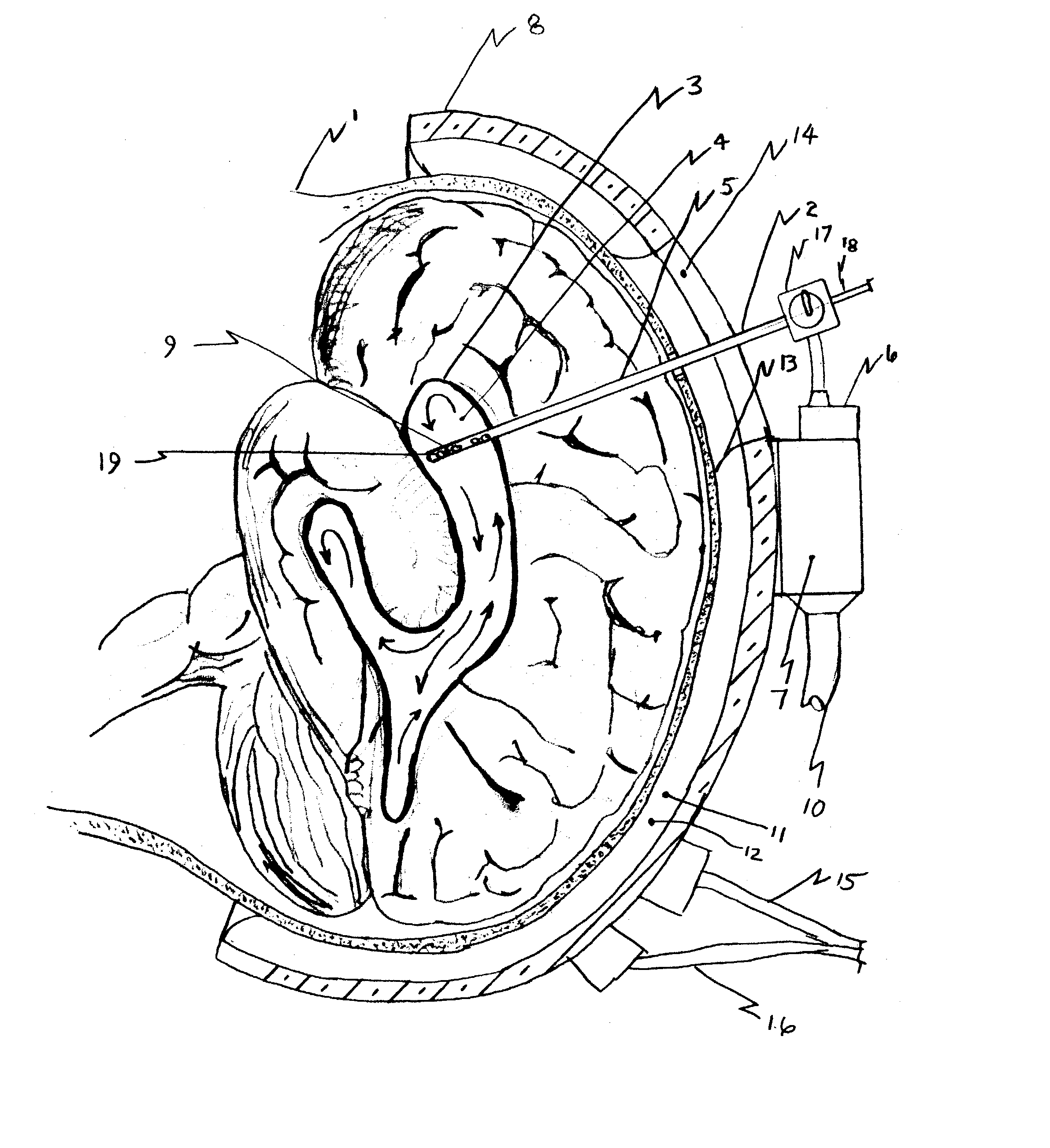
[0052] FIG. 1 depicts a sagittal section of a human head 1 and the normal ventricle-cooling catheter 2 into a operational position in a lateral ventricle of the brain 3. Also shown is the head-cooling cap 8 mounted on the head 1. Cerebrospinal fluid (CSF) 4 is withdrawn from the lateral ventricle 3 through fluid ports 19 in ventricle-cooling catheter shaft 5 into ventricle cooling catheter cooling camber assembly 6 which is then cooled by cooling module 7. Once the CSF is cooled, it is reinserted into lateral ventricle 3 through ventricle-cooling catheter shaft 5. This process is continued in a cyclical manner to obtain and maintain the target temperature of the CSF 4 in ventricle 3 as measured by temperature sensor 9 mounted on the distal end of ventricle-cooling catheter shaft 5. Cooling module 7 is connected to control console (not shown) by umbilical 10. Cooling module 7, cooling chamber assembly 6 and control console (not shown) work in operational relationship to withdraw CSF ...


PUM


Abstract

Disclosed is an apparatus and method for uniform selective cerebral hypothermia. The apparatus includes a brain-cooling probe, a head-cooling cap, a body-heating device and a control console. The brain-cooling probe cools the cerebrospinal fluid within one or more brain ventricles. The brain-cooling probe withdraws a small amount of cerebrospinal fluid from a ventricle into a cooling chamber located ex-vivo in close proximity to the head. After the cerebrospinal fluid is cooled it is then reintroduced back into the ventricle. This process is repeated in a cyclical or continuous manner. The head-cooling cap cools the cranium and therefore cools surface of the brain. The combination of ventricle cooling and cranium cooling provides for whole brain cooling while minimizing temperature gradients within the brain. The body-heating device replaces heat removed from the body by the brain-cooling probe and the head-cooling cap and provides for a temperature difference between the brain and the body where the brain is maintained a temperature lower than the temperature of the body.

Description

[0001] This application is entitled to the benefit of Provisional Patent Application Ser. No. 60 / 344,986 filed Dec. 31, 2001.[0002] 1. Field of Invention[0003] This invention relates to a method, device and system for inducing global cerebral hypothermia while maintaining normal body core temperature for the prevention of secondary brain injury from stroke, trauma, or surgery.[0004] 2. Description of Prior Art[0005] Patients suffering from stroke or head trauma, or have undergone invasive brain or vascular surgery are at risk from secondary brain injury. Secondary brain injury is a result of the innate healing response of the brain to the original insult caused by several not completely understood mechanisms. Regardless of the specific mechanisms involved, the end result is swelling of the brain caused by edema, which can lead to a critical or terminal rise in intra-cranial pressure.[0006] It has long been known that hypothermia is neuroprotective. Hypothermia has a positive affect ...

Claims


Application Information

Patent Timeline
IPC IPC(8): A61B17/00A61F7/00A61F7/02A61F7/12
CPCA61B2017/00084A61F7/12A61F2007/126A61F2007/0056A61F2007/0008A61F7/02
Inventor LENNOX, CHARLES D.
Owner MEDCOOL
Why Eureka
Try Eureka