
Die set with disposable molybdenum die plate and improved window plate for universal gang-punch tool

a technology of molybdenum die plate and window plate, which is applied in the direction of manufacturing tools, metal working apparatus, printed circuit manufacturing, etc., can solve the problems of increasing restrictions on the positioning of the vias in the ceramic greensheet, blockage of the die, and the size of electrical components

Inactive Publication Date: 2003-07-17
GOOGLE LLC
View PDF0 Cites 17 Cited by
  • Summary
  • Abstract
  • Description
  • Claims
  • Application Information

AI Technical Summary

Benefits of technology

0025] In another preferred die of the invention the sub-die plate has a cut-out indent (center-b

Problems solved by technology

With the size of electrical components constantly being reduced through technical improvement, the positioning of the vias in ceramic greensheets is becoming ever more restrictive.
Unfortunately however, the slugs may stick and not fall through the die openings and over time may cause a blockage in the die.
The punch head must then be removed and the broken punch replaced causing costly tool downtime.
Due to the high usage of the gang-punch apparatus, which may be used to punch as many as 10,000 greensheets per day, the die wears rapidly and the die holes wear past there process specification and can no longer be used.
One method to increase die life is to apply coatings to the die but this solution has not been successful since the coating distorts the die.
It was also found that the coatings wore rapidly around the cutting edge of the die and eventually wore past their process limits and / or cracked and flaked off.

Method used


Image

  • Die set with disposable molybdenum die plate and improved window plate for universal gang-punch tool
  • Die set with disposable molybdenum die plate and improved window plate for universal gang-punch tool
  • Die set with disposable molybdenum die plate and improved window plate for universal gang-punch tool

Examples


Embodiment Construction

)

[0044] In describing the preferred embodiment of the present invention, reference will be made herein to FIGS. 1-9B of the drawings in which like numerals refer to like features of the invention. Features of the invention are not necessarily shown to scale in the drawings.

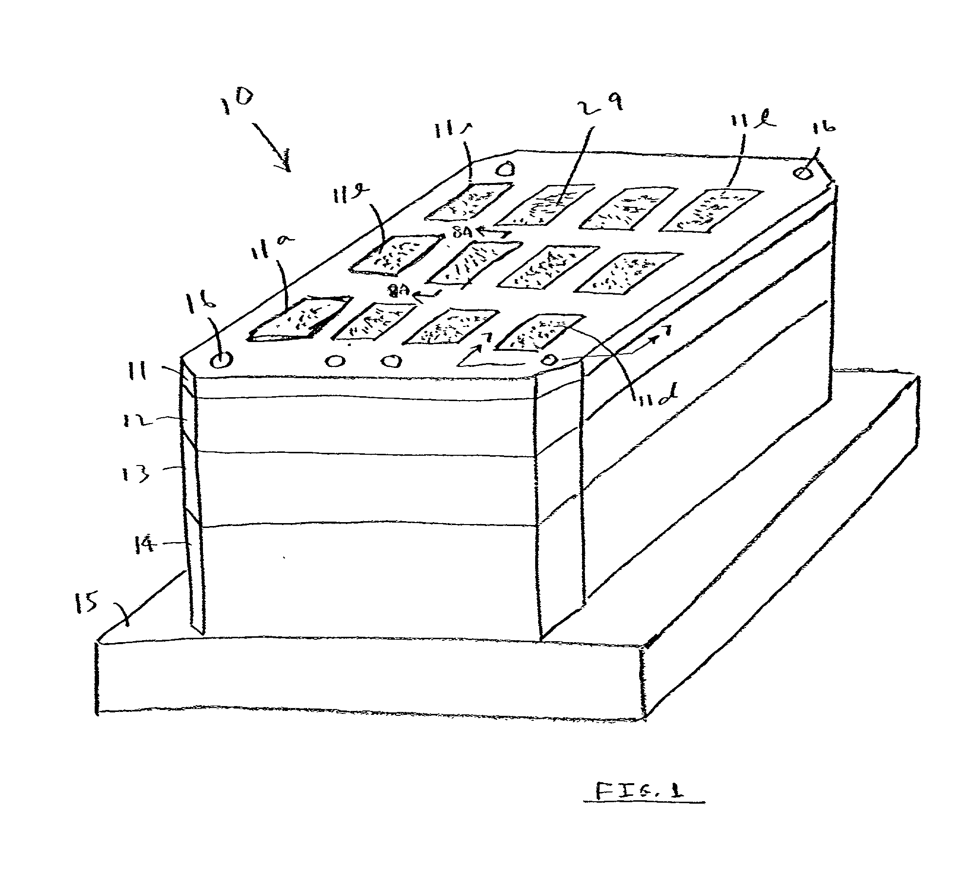
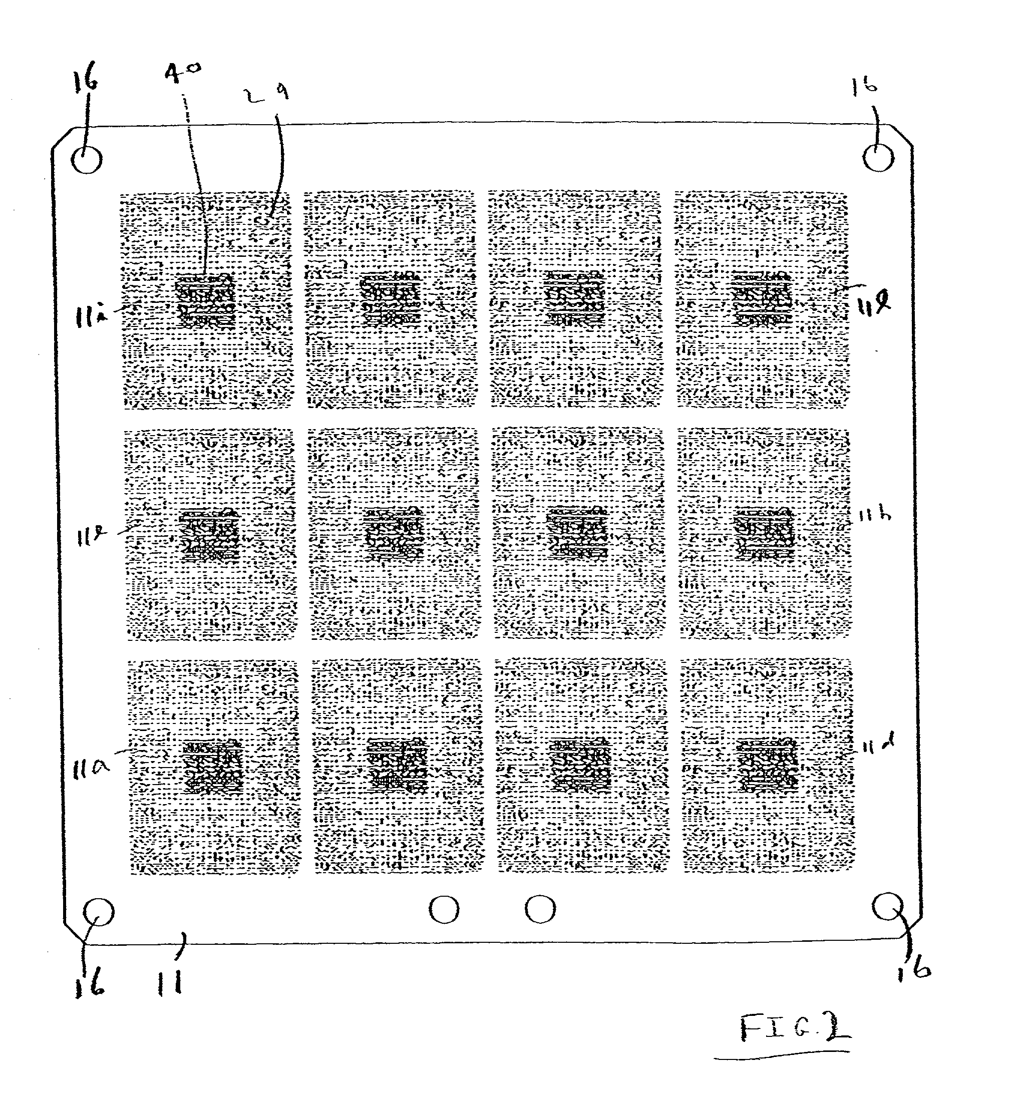
[0045] Referring to FIG. 1, a die of the invention is shown in perspective generally as numeral 10. The die 10 comprises a top (upper) die plate 11 having a number of identical patterns (twelve total) thereon in the shape of greensheets to be punched and the greensheet patterns are shown as 11a-11l and are spaced evenly over the surface of die plate 11. Each pattern will be used to make a ceramic substrate (twelve total). Typically a large greensheet would be placed on the die plate 11 and all twelve (12) individual greensheets 11a-11l formed in one punching operation. After punching, screening, stacking, and lamination, the individual greensheets 11a-11l are cut from the large greensheet laminate and subsequently...


PUM

PropertyMeasurementUnit
Diameteraaaaaaaaaa
Electrical resistanceaaaaaaaaaa
Areaaaaaaaaaaa

Abstract

A die and method of gang punching selective holes in thin sheet materials such as greensheets are provided in which slugs of greensheet material formed during the punching operation easily fall through the die and are removed. The die uses a number of plates one of which is a window plate having openings correspond to openings in a die plate disposed thereon. The window plate openings have a larger diameter than the die plate openings and also a plurality have an oval shape which oval shape openings provide less resistance to the falling slugs and facilitate removal of the slugs from the die. The window plate also preferably has a central grid open area with the remainder of the plate having vertical through-holes corresponding to the through-holes of the die plate. The die also preferably employs a die plate made from at least two sheets of material, i.e., an upper disposable sheet (die plate) and a lower sheet (sub-die plate) wherein the upper die plate is made from a wear-resistant material such as molybdenum. The upper die plate is preferably made by photolithography techniques.

Description

[0001] 1. Field of the Invention[0002] This invention relates to an apparatus and method for punching holes in thin sheet material and, more particularly, to a die used with a gang-punch apparatus for punching holes in a desired hole pattern in a greensheet used in the manufacture of electronic components.[0003] 2. Description of Related Art[0004] In the manufacture of multilayer ceramic (MLC) substrates for integrated circuit semiconductor package structures, a plurality of green ceramic sheets (commonly termed greensheets) are formed by doctor blading a slurry containing a resin binder, a particulate ceramic material, solvents and a plasticizer, drying the doctor bladed sheet and cutting it into appropriate size sheets. Through-holes, commonly termed vias, are then punched in the greensheets to facilitate forming electrical interconnections through the sheet. Electrically conductive paste is deposited in the holes and in appropriate patterns on the surface of each of the greenshee...

Claims


Application Information

Patent Timeline
IPC IPC(8): B26D7/18B26F1/14H05K3/00
CPCB26D7/1863H05K3/005B26F2210/08B26F1/14Y10T83/04Y10T83/943Y10T83/9476Y10T83/883
Inventor BALZ, JAMES G.LAPLANTE, MARK J.LONG, DAVID C.WEISS, THOMAS
Owner GOOGLE LLC
Features
  • Generate Ideas
  • Intellectual Property
  • Life Sciences
  • Materials
  • Tech Scout
  • Unparalleled Data Quality
  • Higher Quality Content
  • 60% Fewer Hallucinations
Learn More