

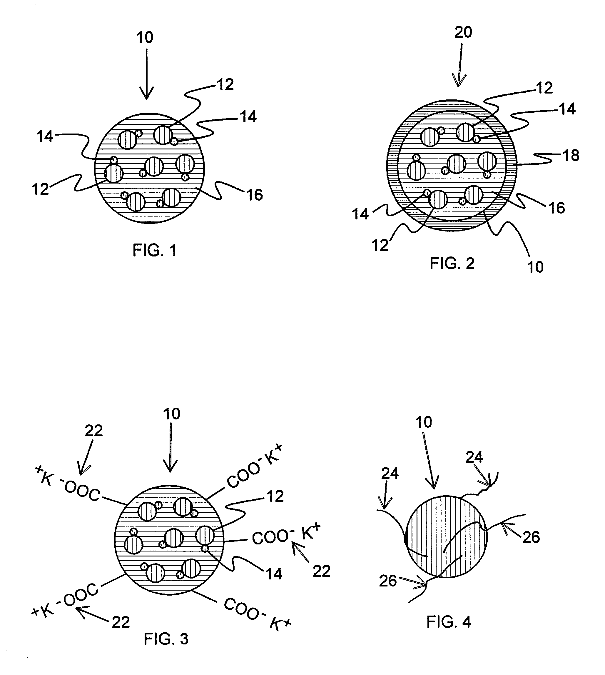
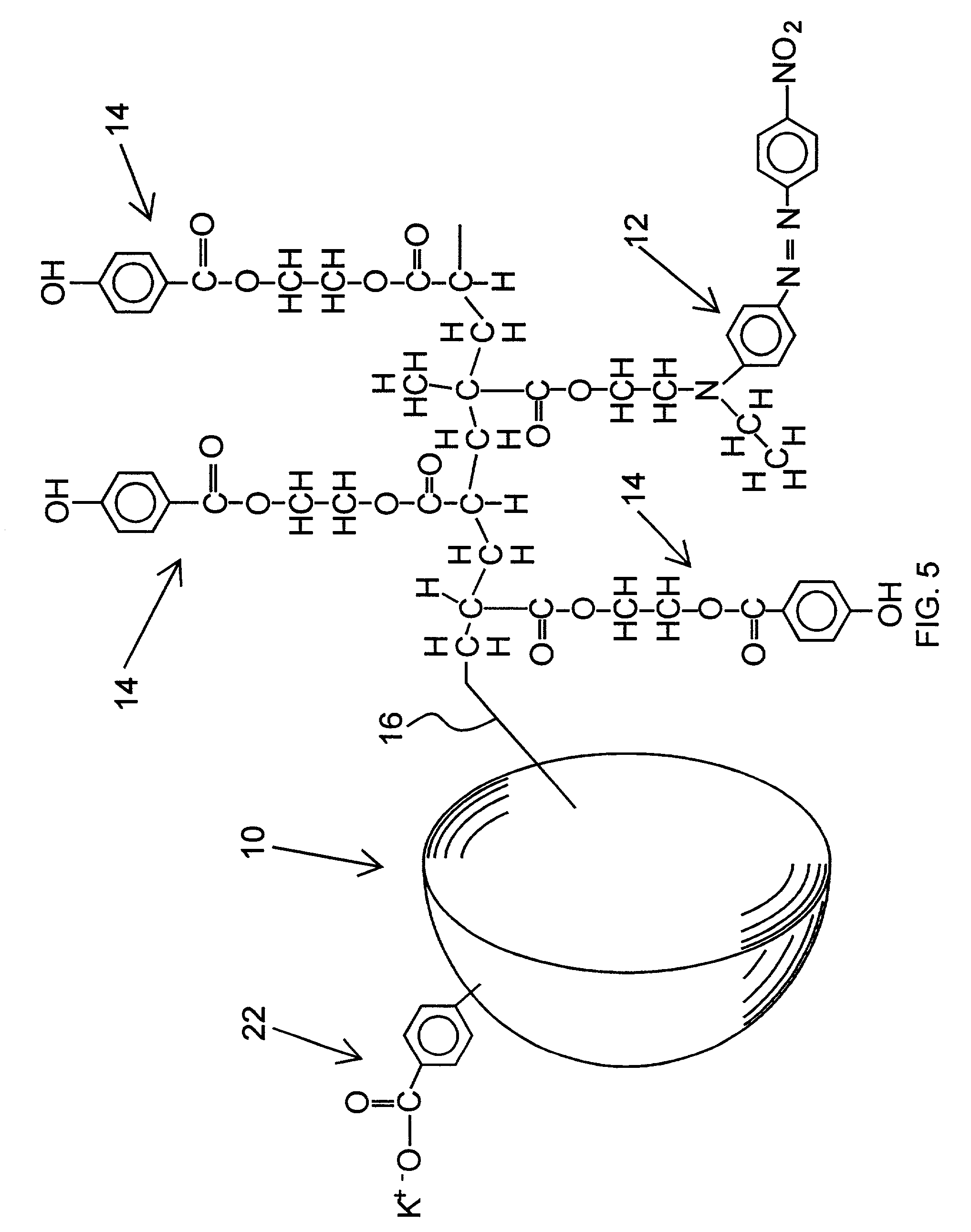
Encapsulated dye particle
a dye particle and dye technology, applied in the field of encapsulated dye particles, can solve the problems of poor bleed control, numerous print durability disadvantages, poor print waterfastness, etc., and achieve the effect of providing durability of printed ink without significant viscosity increas
- Summary
- Abstract
- Description
- Claims
- Application Information
AI Technical Summary
Benefits of technology
Problems solved by technology
Method used
Image

Examples
example 1
[0055] The following is an exemplary chemistry and synthetic process for fabricating an encapsulated dye particle for an aqueous-based ink (without a photostabilizer):
[0056] Pre-Emulsion Monomer Mix:
[0057] 2 gm Neozapon Red 335 (water insoluble) dye
[0058] 10 gm methyl methacrylate
[0059] 1 gm methacryloyloxy ethyl succinate (particle dispersant reacted into particle)
[0060] 3 gm deionized water
[0061] 1 gm 30% Rhodafac RS710 surfactant in deionized water
[0062] Reaction Bath:
[0063] 34 gm deionized water
[0064] 0.1 gm potassium persulfate (thermal initiator)
[0065] The pre-emulsion was formed by adding each of the listed ingredients in the order given. The reaction bath was prepared by heating the water in a three-necked flask to 90.degree. C. The thermal initiator was subsequently added to the reaction bath. The pre-emulsion solution was drop-wise added to the reaction bath over a 10 minute period using an addition funnel. The reaction bath was continuously stirred by a mechanical stirrer...
PUM
| Property | Measurement | Unit |
|---|---|---|
| Diameter | aaaaa | aaaaa |
| Diameter | aaaaa | aaaaa |
| Transparency | aaaaa | aaaaa |
Abstract
Description
Claims
Application Information