Liquid crystal display device and liquid crystal projector device

a liquid crystal display and projector technology, applied in the direction of picture reproducers, television systems, instruments, etc., can solve the problems of noise generation, deterioration of reliability, and worry, and achieve the effect of high heat conductivity and efficient cooling

Inactive Publication Date: 2003-08-07
SONY CORP
View PDF4 Cites 25 Cited by
  • Summary
  • Abstract
  • Description
  • Claims
  • Application Information

AI Technical Summary

Benefits of technology

[0009] An object of the present invention is to provide a new liquid crystal display device and liquid crystal projector device, which can solve the problems that the above-mentioned conventional device has.
[0010] Another object of the invention is to provide a liquid crystal display device and a liquid crystal projector device, which can prevent deterioration of its reliability coming up with increase of temperature or increase of light quantity.
[0011] Still another object of the invention is to provide a liquid crystal display device and a liquid crystal projector device, which can efficiently cool a structure including a liquid crystal panel, and further a method of cooling a panel of the liquid crystal panel.
[0013] The liquid crystal display device according to the invention mounts a liquid crystal panel on a light incident plane of a prism in a bonded state and integrates the panel with the prism, and forcedly cools this integrated structure statically by cooling means. Accordingly, it becomes possible to cool the liquid crystal panel efficiently without bringing any trouble caused by fan noise or floating dust. In addition, in regard to the liquid crystal projector device using a liquid crystal panel as its liquid crystal light valve, if the same construction as the above is adopted, it becomes possible to cool the liquid crystal light valve efficiently without bringing any trouble caused by fan noise or floating dust.
[0015] In the liquid crystal display device and the liquid crystal projector device according to the invention, a liquid crystal panel is mounted in a bonded state on the light incident plane of the prism through a transparent substrate having high heat conductivity and integrated with the prism. Accordingly, heat generated at the liquid crystal panel is absorbed by the transparent substrate and the absorbed heat is diffused by the prism. Thus, the liquid crystal panel is efficiently cooled with the prism used as a cooling bath.

Problems solved by technology

Therefore, there has been worry about deterioration of reliability owing to increasing temperature or increasing quantity of light.
However, in the air-cooling method, there have been inconveniences such that noises are generated by rotations of the fan or dust rises.
In the liquid-cooling method, it is necessary to dispose a liquid-cooling container around the liquid crystal light valve, which disadvantages in regard to miniaturizing.
Therefore, cooling effect easily becomes uneven.
Furthermore, there is a problem in that sufficient cooling effect is not easily obtained.
In particular, as the distance between optical members becomes short owing to miniaturizing, the environmental temperature increases accordingly.
Thus, cooling effect is expected to deteriorate.
In those cases, the conventional air-cooling method or liquid cooling method cannot restrain the temperature of the liquid crystal light valve from increasing any more, so that it will be further difficult to retain reliability thereof.

Method used


Image

  • Liquid crystal display device and liquid crystal projector device
  • Liquid crystal display device and liquid crystal projector device
  • Liquid crystal display device and liquid crystal projector device

Examples


first embodiment

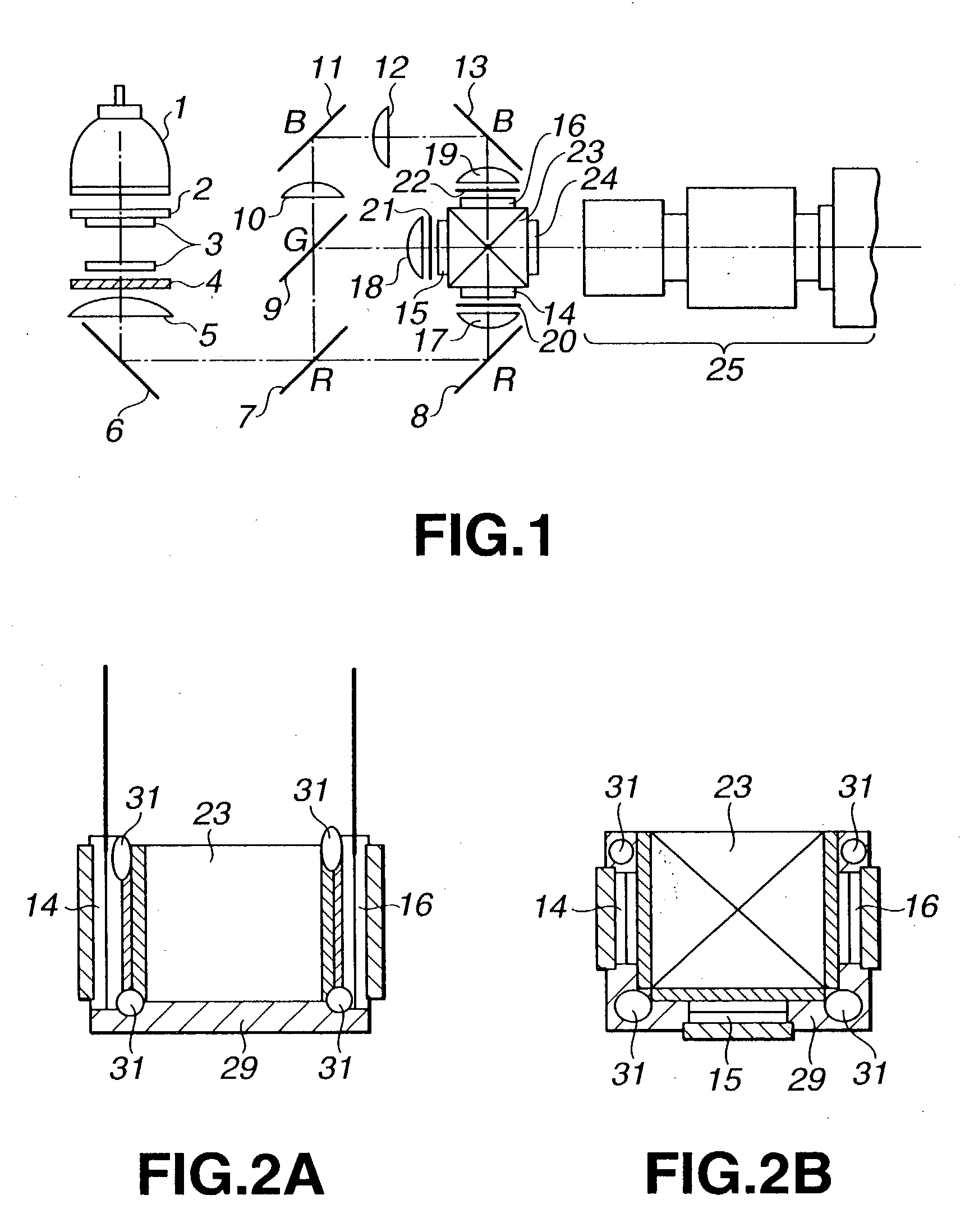
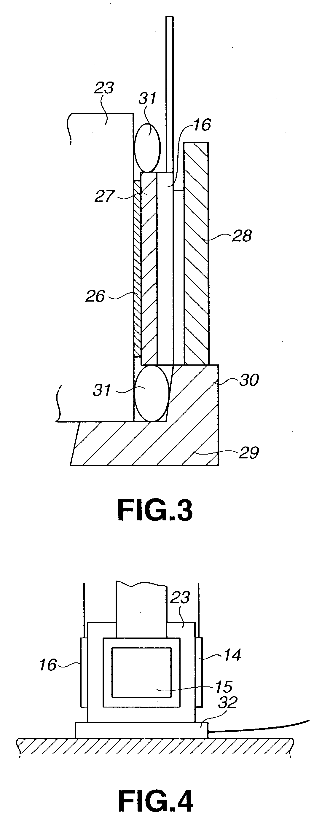
[0043] FIGS. 2A and 2B show an example of a main part of a construction of the liquid crystal projector device according to the invention. FIG. 2A is a side view thereof, and FIG. 2B is a plan view thereof. FIG. 3 is a cross-sectional view showing a main part of the construction of mounting the liquid crystal panel in an manner of enlarging.

[0044] On the three planes of light incidence in the dichroic prism 23, as shown in FIGS. 2B and 3, the liquid crystal panels 14, 15 and 16 are mounted in a bonded manner, respectively. By doing so, the dichroic prism 23 and the liquid crystal panels 14, 15 and 16 are integrated with each other. Further, a cooling means is disposed around the dichroic prism 23 so as to forcedly cool the integrated structure constituted by the relevant dichroic prism 23 and the liquid crystal panels 14, 15 and 16 statically.

[0045] Hereinafter, a specific construction of mounting the liquid crystal panels 14, 15 and 16 to the dichroic prism 23 and a structure of th...

second embodiment

[0061] Incidentally, in the liquid crystal projector device of the second embodiment described here, the Peltier cooling component 32 is used as the heat sink. However, instead of the Peltier cooling component 32, the heat pipe 31 may be used as shown in the side view FIG. 5A and the bottom view FIG. 5B, for example. By drawing the heat pipe 31 on the bottom face of the dichroic prism 23 in a state of being contact with the relevant bottom face, the same effect as one described above can be obtained. Further, by drawing the heat pipe 31 in the form of surrounding the periphery of each of the liquid crystal panels 14, 15 and 16, the heat generated at the respective liquid crystal panels 14, 15 and 16 is sucked by the heat pipe 31, thereby obtaining a high cooling effect.

[0062] A third embodiment of the liquid crystal projector device according to the invention now will be described. This liquid crystal projector device is constructed, in the same manner as one described in the second...

fourth embodiment

[0073] the liquid crystal projector device according to the invention now will be described with reference to drawings.

[0074] This liquid crystal projector device is also constructed, in the same manner as one described in the first to third embodiments, in that the respective liquid crystal panels 14, 15 and 16 are mounted on three light incident planes of the dichroic prism 23 in a bonded state as shown in FIG. 11. With this structure, the dichroic prism 23 and the respective liquid crystal panels 14, 15 and 16 are integrated with each other.

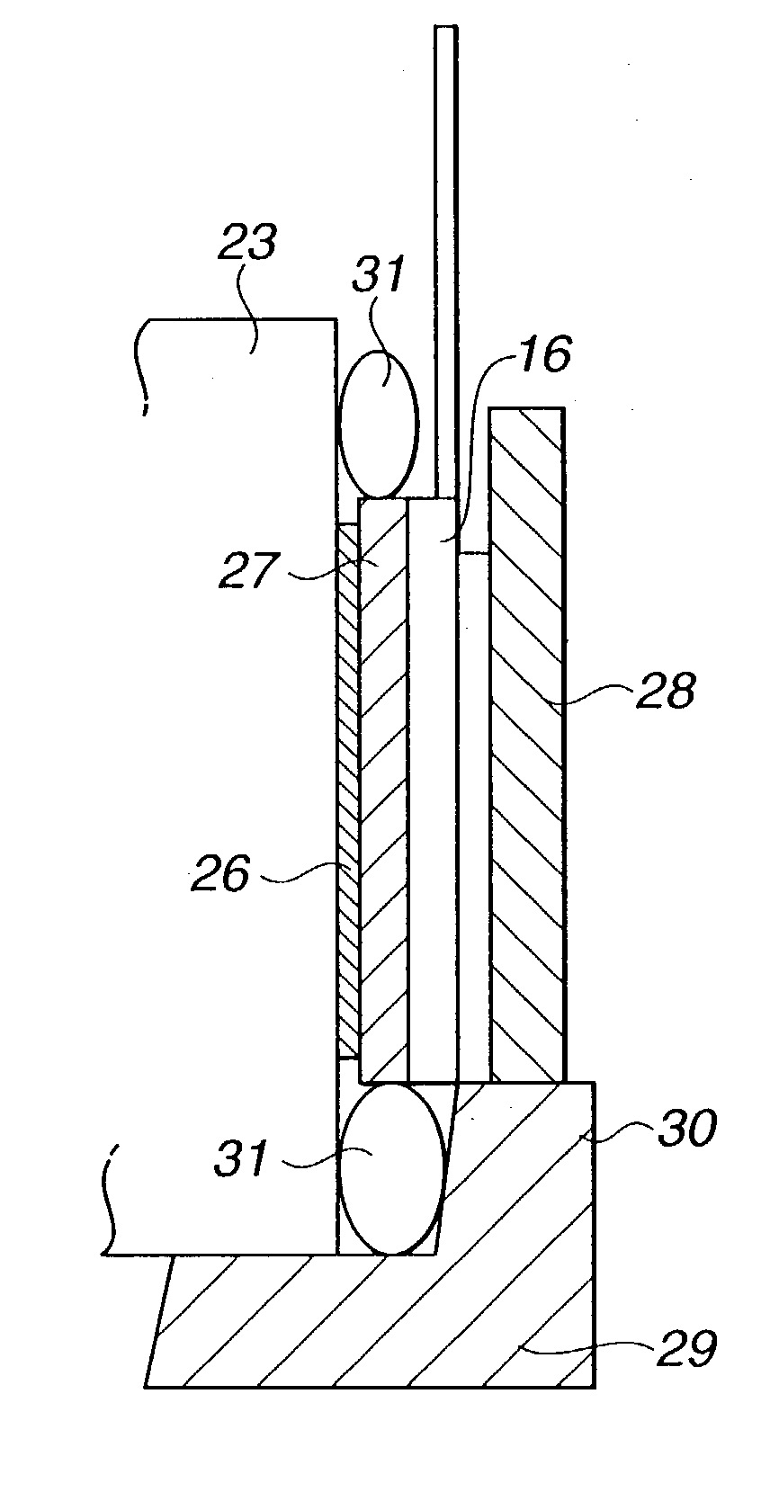
[0075] Hereinafter, a specific construction of mounting the liquid crystal panels 14, 15 and 16 to the dichroic prism 23 will be described with the liquid crystal panel 16 shown in FIG. 12 used as an example.

[0076] Between the dichroic prism 23 and the liquid crystal panel 16, the polarizing plate 26 and the transparent glass substrate 27 are interposed. The transparent glass substrate 27 to be used in the embodiment is desirably made of subst...


PUM

PropertyMeasurementUnit
transparentaaaaaaaaaa
refractive indexaaaaaaaaaa
heat conductivityaaaaaaaaaa

Abstract

The present invention is a liquid crystal projector device using a liquid crystal panel. The device mounts a liquid crystal panel (16) on a light incident plane of a polyhedral dichroic prism (23) in a bonded state so as to integrate the panel with the prism, and comprises a heat sink (29) and a heat pipe (31) which forcedly cools the integrated structure statically. The liquid crystal projector device comprising the structure describe above cools the liquid crystal panel efficiently without bringing any trouble caused by fan noise or raise of dust.

Description

TECHNICAL FIELD[0001] The present invention relates to a liquid crystal display device and a liquid crystal projector device, and further to a panel cooling method.BACKGROUND ART[0002] In these days, a liquid crystal projector device using a liquid crystal panel as a liquid crystal light valve therein has been developed evidently. As the liquid crystal projector device, there are mainly considered a data projector device configured for a personal computer, a front projector device configured for a home theater, and further, there is considered a rear projector device configured for a rear projection television.[0003] The liquid crystal projector device is roughly divided into two types, that is, a single-panel type which uses a liquid crystal light valve (liquid crystal panel) with color filters of three colors, i.e., R (red), G (green) and B (blue), and a three-panel type which uses three monochrome liquid crystal light valves (liquid crystal panels) for three optical paths of R, G...

Claims


Application Information

Patent Timeline
Patent Type & Authority Applications(United States)
IPC IPC(8): G02F1/133G03B21/00H04N5/74H04N9/31
CPCG02F1/133385G03B21/00H04N5/7441H04N9/3197H04N9/3141H04N9/3144H04N9/3105G03B21/006G02F1/13
Inventor KAISE, KIKUOKOBAYASHI, MIKIYANISHIHARA, SHIZUO
Owner SONY CORP
Why Eureka
Try Eureka