Rotary driving insertion connection, particularly for transmitting torque in a drivetrain of a motor vehicle

a technology of insertion connection and drivetrain, which is applied in the direction of mechanical actuator clutches, couplings, mechanical apparatus, etc., can solve the problems of intensive engine vibration, annoying rattling noise, and noise of intensive engine vibration

Inactive Publication Date: 2003-08-14
ZF SACHS AG
View PDF9 Cites 6 Cited by
  • Summary
  • Abstract
  • Description
  • Claims
  • Application Information

AI Technical Summary

Benefits of technology

[0006] Insofar as there is no direct positive rotary driving engagement between the inner circumference and the outer circumference, the coupling elements allow additional degrees of freedom for solving the problems confronting the designer. For example, the coupling elements make it possible to design the rotary driving insertion connection in such a way that torque can be transmitted via the rotary driving insertion connection substantially without play and, therefore, substantially without noise, while preserving simplicity of assembly to a great extent. For this purpose, the coupling elements preferably have movement play between the inner circumference and the outer circumference and can be displaced into an engagement position in which they bring about a positive rotary driving engagement between the inner circumference and the outer circumference substantially without play. The coupling elements bring about the positive rotary driving engagement substantially without play only in the engagement position, and it can be provided that the coupling elements are only displaced or displaceable to the engagement position after assembly, possibly only during operation, or that the coupling elements can be displaced out of the engagement position into an assembly position, for example, for assembly.
[0009] It is ensured that expenditure on assembly is comparatively small or at least not excessive in that, for example, at least a portion of the plurality of coupling elements is grouped into a coupling element group that can be handled as a unit by means of a grouping arrangement which limits the movement play of the coupling elements relative to one another and / or which connects the coupling elements to one another, and / or at least a portion of the plurality of coupling elements is held by means of a / the grouping arrangement in a reference position (possibly the assembly position) relative to the associated inner circumference and / or relative to the associated outer circumference. For this purpose, the grouping arrangement can include a coupling element cage. The coupling element cage can advantageously be constructed so as to be radially elastic or radially flexible and / or can ensure axial and / or radial play of the coupling elements.

Problems solved by technology

Annoying rattling noises can occur as a result of engine vibrations, particularly when the engine is idling.
For example, there is a risk of intensive engine vibrations and, therefore, annoying rattling noises when the insertable shaft connection is provided between a clutch or dual clutch and a dual mass flywheel, since in this case the clutch or dual clutch is generally the secondary-side flywheel mass of the dual mass flywheel.
Further, there is also a risk of intensive engine vibrations and, consequently, annoying rattling noises, for example, when the insertable shaft connection is provided between a drive unit (particularly a combustion engine) and a torque converter, since the converter generally forms the flywheel mass of the drive unit (of the engine).

Method used


Image

  • Rotary driving insertion connection, particularly for transmitting torque in a drivetrain of a motor vehicle
  • Rotary driving insertion connection, particularly for transmitting torque in a drivetrain of a motor vehicle
  • Rotary driving insertion connection, particularly for transmitting torque in a drivetrain of a motor vehicle

Examples


Embodiment Construction

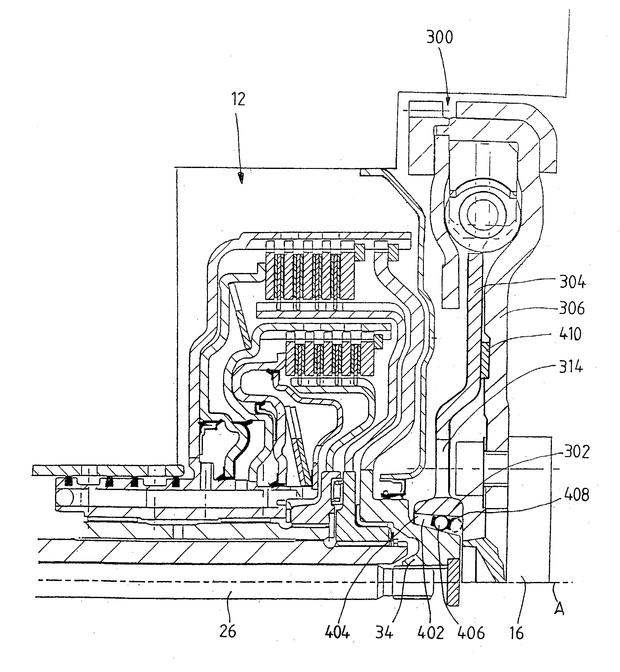
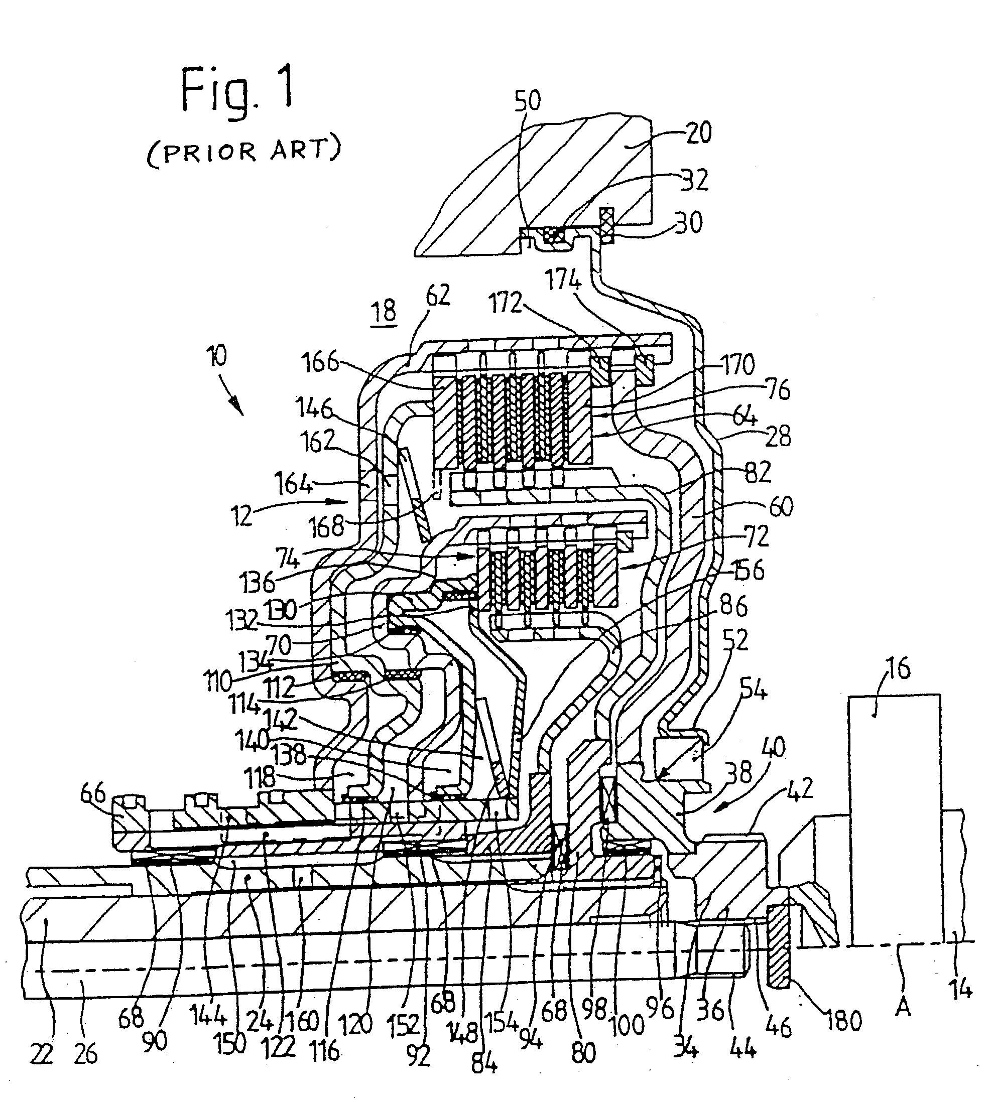
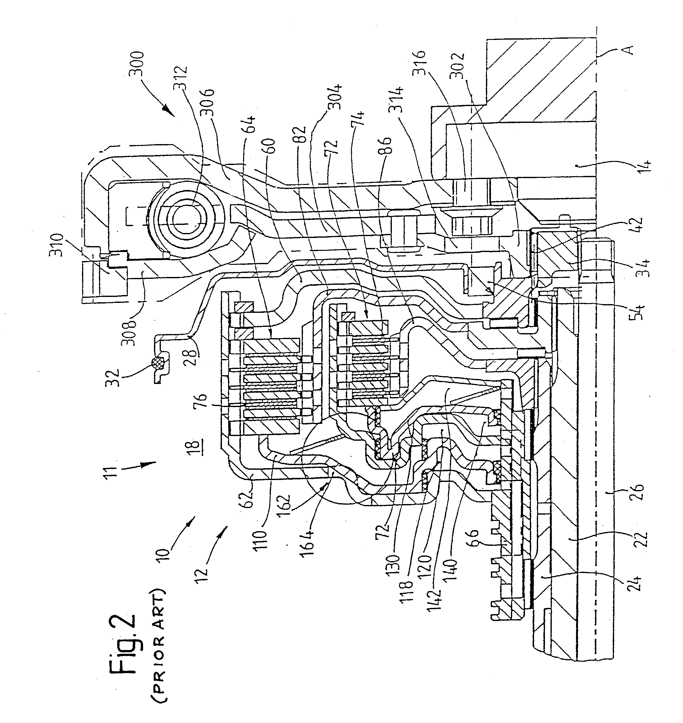
[0040] FIG. 1 shows a dual clutch 12 arranged in a drivetrain 10 between a drive unit and a transmission. A drive unit, e.g., an internal combustion engine, is indicated in FIG. 1 only by a driven shaft 14, possibly a crankshaft 14, with a coupling end 16 for coupling to a torsional vibration damper, not shown. The transmission is illustrated in FIG. 1 by a transmission housing portion 20 defining a transmission bell housing 18 and two transmission input shafts 22 and 24, both of which are constructed as hollow shafts. Transmission input shaft 22 extends through the transmission input shaft 24 substantially coaxial to the latter. A pump drive shaft which serves to drive a transmission-side oil pump, not shown in FIG. 1, is arranged in the interior of the transmission input shaft 22.

[0041] A coupling hub 34 which extends through a central opening of the cover 28 in the direction of the drive unit and is coupled with the torsional vibration damper, not shown, by means of an external t...


PUM


Abstract

A rotary driving insertion connection, particularly for transmitting torque in a drivetrain of a motor vehicle between components or units of the drivetrain which are connected or are to be brought into a connection for transmitting torque, comprises a primary-side coupling area at a first component and a secondary-side coupling area at a second component. One of the coupling areas has a cutout which is defined by an inner circumference or at least an inner circumferential portion, and the other coupling area has at least one projecting portion having an outer circumference or at least an outer circumferential portion which is inserted or can be inserted into the cutout axially with reference to an axis of rotation in order to provide a positive rotary driving engagement between the inner circumference and the outer circumference. A plurality of coupling elements producing the positive rotary driving engagement is provided between the inner circumference and the outer circumference.

Description

[0001] 1. Field of the Invention[0002] The invention is directed generally to an axial insertion assembly connection for rotary driving or transmission of torque between components or units, e.g., of a drivetrain in a motor vehicle, for example, between a combustion engine and a torque transmission device (for example, a friction clutch, a dual clutch or a torque converter), possibly with the intermediary of a torsional vibration damper or a dual mass flywheel. Somewhat more concretely, the invention is directed to a rotary driving insertion connection, particularly for transmitting torque in a drivetrain of a motor vehicle between components or units of the drivetrain which are connected or are to be brought into a connection for transmitting torque, comprising a primary-side coupling area at a first component and a secondary-side coupling area at a second component, at least one of which has a cutout which is defined by an inner circumference or at least an inner circumferential p...

Claims


Application Information

Patent Timeline
Patent Type & Authority Applications(United States)
IPC IPC(8): F16D1/108F16D21/06F16D25/0635F16D25/10
CPCF16D1/108F16D25/10F16D25/0635F16D25/0638F16D21/06
Inventor KUNDERMANN, WOLFGANGKUHSTREBE, JOCHENREISSER, WOLFGANG
Owner ZF SACHS AG
Why Eureka
Try Eureka