Radiation detector arrangement
a detector arrangement and radiation detector technology, applied in the field of gaseous-based ionizing radiation detectors, can solve the problems of time-consuming and impractical scanning-based two-dimensional detection, image useless or at least, severely reducing the spatial resolution obtained
- Summary
- Abstract
- Description
- Claims
- Application Information
AI Technical Summary
Benefits of technology
Problems solved by technology
Method used
Image
Examples
first embodiment
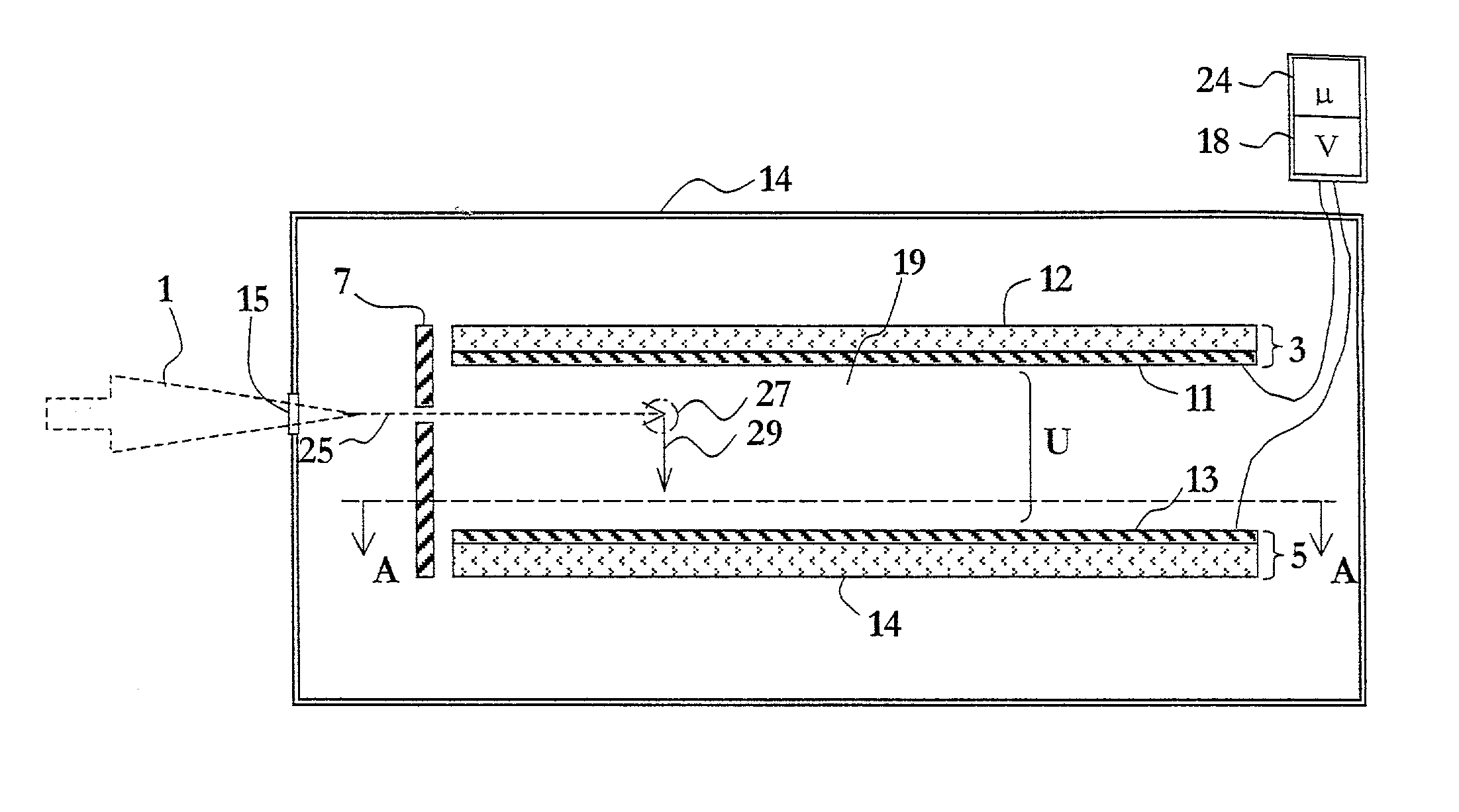
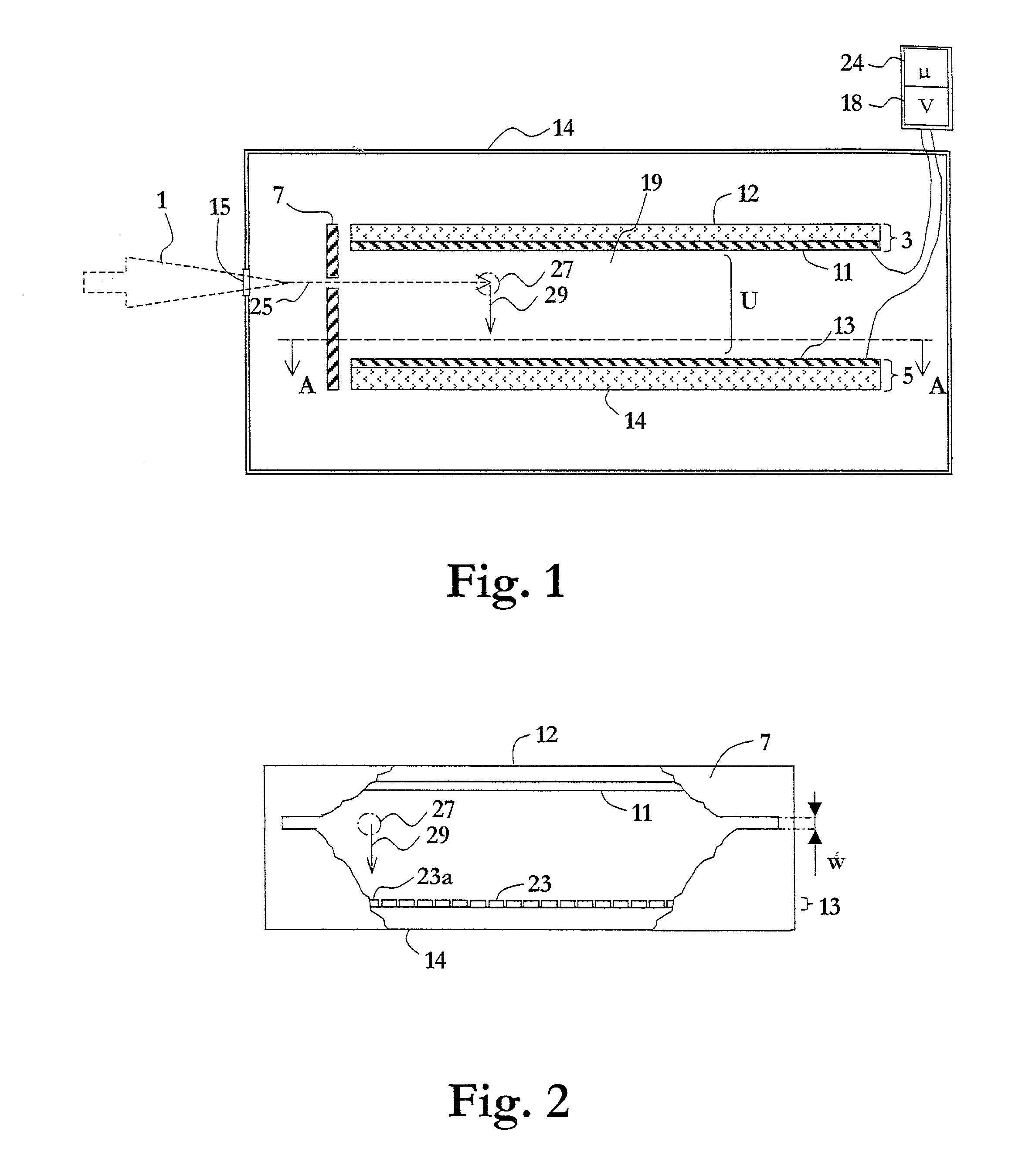
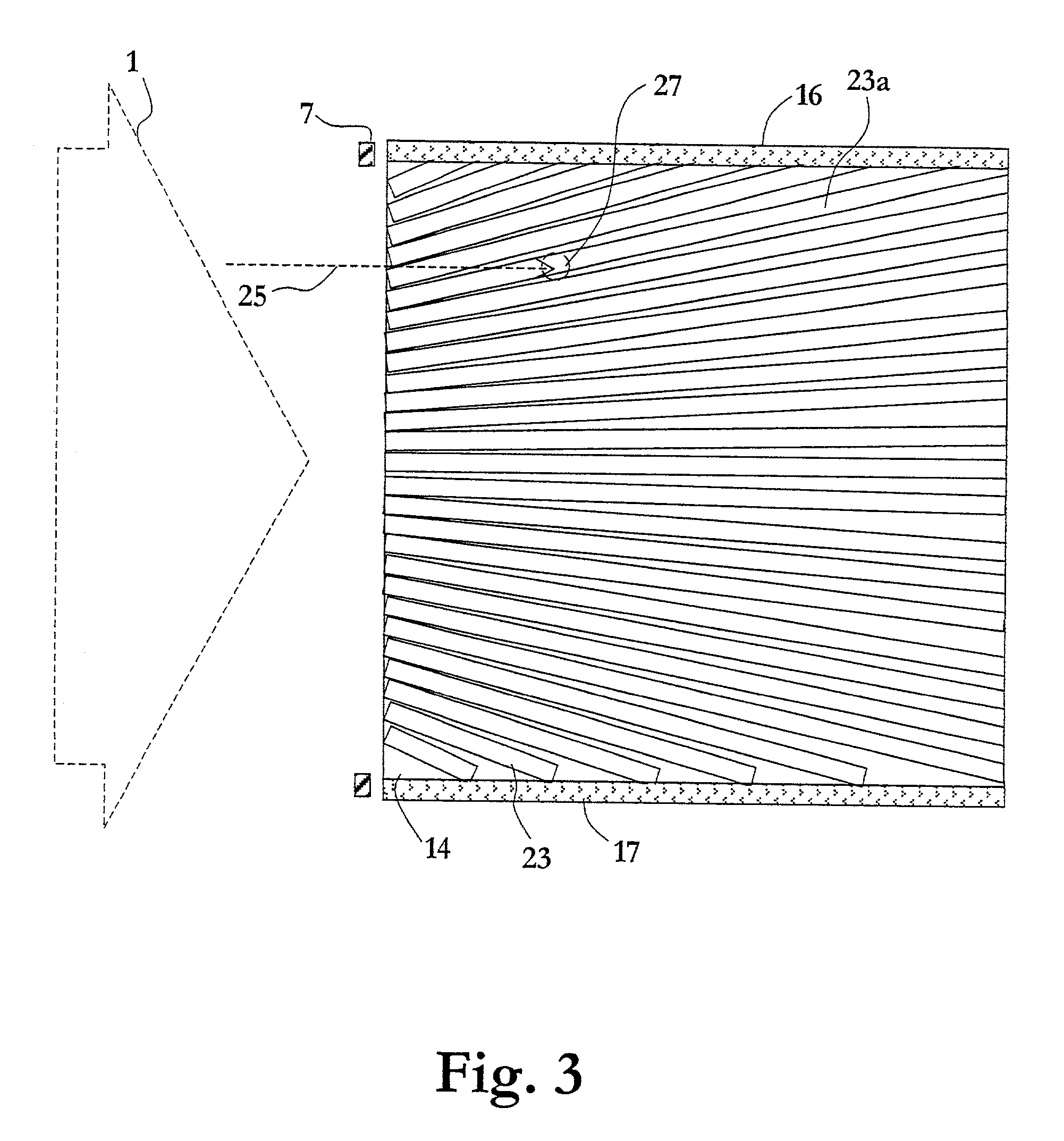
[0039] With reference now to FIG. 4a, which illustrates schematically, in a front view, an X-ray scanning-based detector arrangement including a plurality of the detector unit of FIGS. 1-3 the present invention will be described. The arrangement is preferably aimed for acquisition of series of images of lower quality to observe time dependent examination such as e.g. positioning of catheters or of series of images of higher quality at high speed to visualize moving objects, such as e.g. heart, blood, etc., in detail. From the series single images can be extracted for detailed analysis. The arrangement includes a plurality of line detector units 41, 41a arranged on a common circular support structure 42 in a two-dimensional array with their respective entrance slits 43, 43a facing the front of the arrangement. For illustrative purposes FIG. 4a includes a matrix of 24 detector units: twelve wider detector units 41 symmetrically arranged in a circle on the support 42 and twelve narrowe...
third embodiment
[0050] With reference next to FIG. 6, which illustrates schematically, in a front view, an X-ray scanning-based detector arrangement, the present invention will be overviewed, which in fact is capable of detecting also at its center.
[0051] Twelve wider detector units 41 are arranged on a circular support 62 with their respective entrance slits 43 aiming towards the radiation source used. The units 41 are here arranged in a circle, schematically indicated by 63, which is smaller and eccentrically located with respect to the circular support 62. The detector arrangement is rotatable around an axis centrally located with respect to the circular support 62 by means of a spindle mounted to the back of the detector arrangement and schematically indicated in FIG. 6 by a dashed circle 64. Note that the entrance slit of one of the detector units is overlying the central axis for the rotation and the individual readout element detecting radiation incident along this central axis will detect t...
fourth embodiment
[0053] With reference next to FIG. 7, which illustrates schematically, in a front view, an uncomplicated scanning-based detector arrangement, the present invention will be depicted.
[0054] Here, the detector arrangement includes a single line detector unit 41 including an entrance slit 43 in the front across the complete diameter of a circular dielectric substrate 72 and two shorter line detector units 41a, each including an entrance slit 43a in the front, arranged orthogonal to the longer detector unit 41. A driving wheel 74 is arranged to engage with the circular dielectric substrate 72 such that the detector array can be rotated in the plane of the detector units by wheel 74, and thus without mounting a central axis to the detector arrangement. The circular dielectric substrate 72 may for instance be mounted in a bearing or similar (not illustrated).
[0055] Such solution is preferably used for any collimators used such that a central axis would not block radiation.
[0056] The detect...
PUM
 Abstract
Description
Claims
Application Information
 - R&D
- Intellectual Property
- Life Sciences
- Materials
- Tech Scout
- Unparalleled Data Quality
- Higher Quality Content
- 60% Fewer Hallucinations
Browse by: Latest US Patents, China's latest patents, Technical Efficacy Thesaurus, Application Domain, Technology Topic, Popular Technical Reports.
© 2025 PatSnap. All rights reserved.Legal|Privacy policy|Modern Slavery Act Transparency Statement|Sitemap|About US| Contact US: help@patsnap.com


