Linear electric field time-of-flight ion mass spectrometer

a time-of-flight ion and mass spectrometer technology, applied in the field of mass spectrometers, can solve the problems of limiting the use of mass spectrometers to a narrow mass range, high mass of magnets and the time required to scan the entire mass range one mass, and poor spatial resolution it provides

Inactive Publication Date: 2008-06-10
RGT UNIV OF CALIFORNIA
View PDF2 Cites 4 Cited by
  • Summary
  • Abstract
  • Description
  • Claims
  • Application Information

AI Technical Summary

Problems solved by technology

Major limitations on this type of mass spectrometer are the high mass of the magnet and the time that is required to scan the entire mass range one mass at a time.
While this type of spectrometer can detect multiple mass-per-charge species can be detected simultaneously, the poor spatial resolution it provides limits its use to a narrow mass range.
Major limitations of quadrupole mass spectrometers are the high mass of mass of the required magnet and the time required to scan the entire mass range one mass at a time.
A further limitation of conventional mass spectrometry lies in the fact that the source of ions is a separate component from the time-of-flight section of a spectrometer, and it requires significant resources.
First, most ion sources are inherently inefficient, so that few atoms or molecules of a gaseous sample are ionized, thereby requiring a large volume of sample and, in order to maintain a proper vacuum, a large vacuum pumping capacity.
Second, the ion source typically generates a continuous ion beam that is gated periodically, creating an inefficient condition in which sample material and electrical energy are wasted during the time the gate is “closed.” Third, ions have to be transported from the ion source to the time-of-flight section, requiring, among other things, electrostatic acceleration, steering and focusing.
Fourth, typical ion sources introduce a significant spread in energy of the ions so that the ions must be substantially accelerated to minimize the effect of this energy spread on the mass resolving power.
Still another problem with conventional time-of-flight mass spectrometers is that ions must be localized in space at time t1 in order to minimize Δd and, therefore, minimize the mass resolving power.
In summary, the limitations on conventional TOFMS include a mass resolving power dependent on the energy spread of the ions emitted from the ion source; the uncertainty in the distance of travel of the ion in its flight path; the problems associated with an ion source that is separate from the drift region; and the need to localize ions in space at time t1.

Method used


Image

  • Linear electric field time-of-flight ion mass spectrometer
  • Linear electric field time-of-flight ion mass spectrometer
  • Linear electric field time-of-flight ion mass spectrometer

Examples


Embodiment Construction

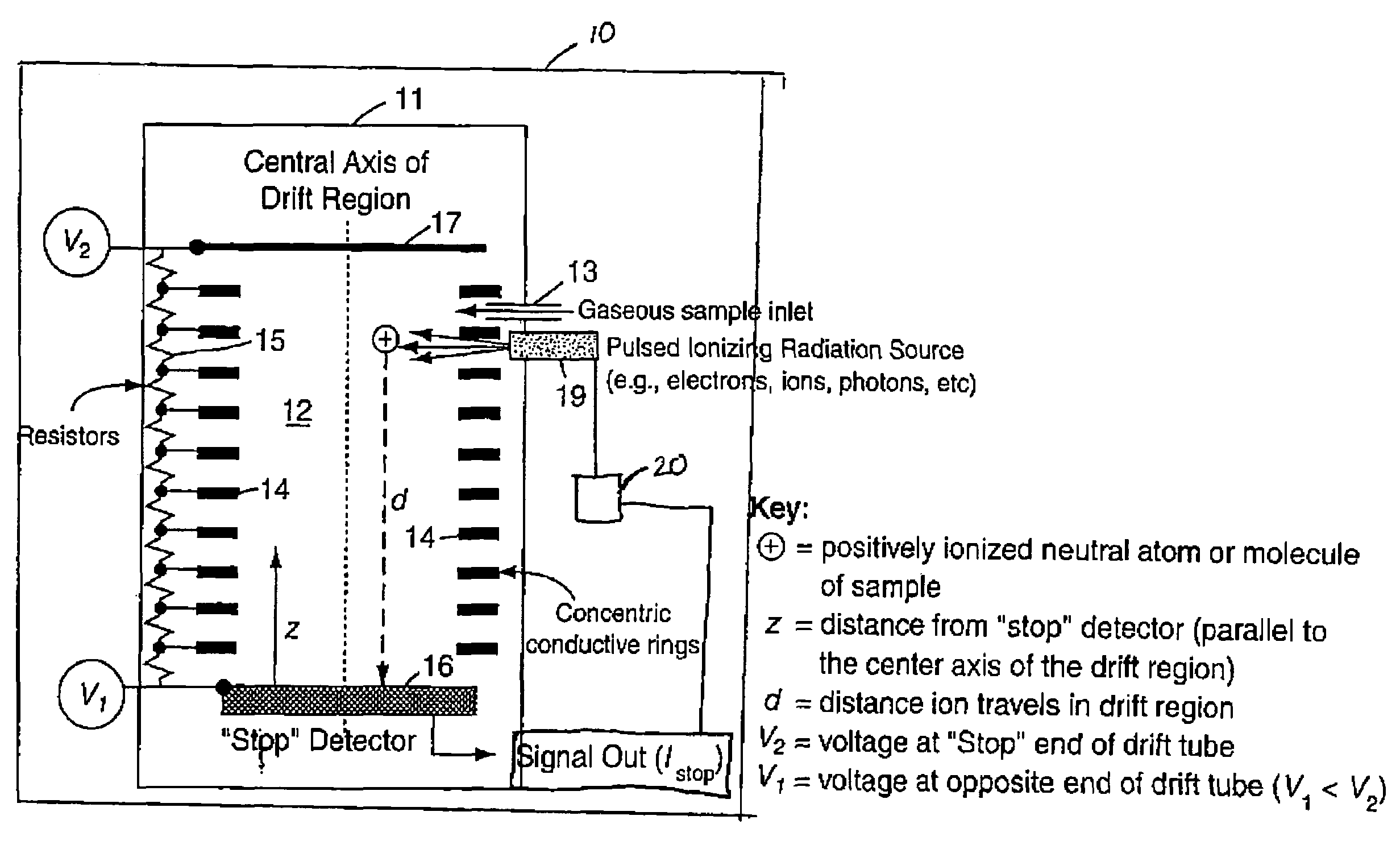
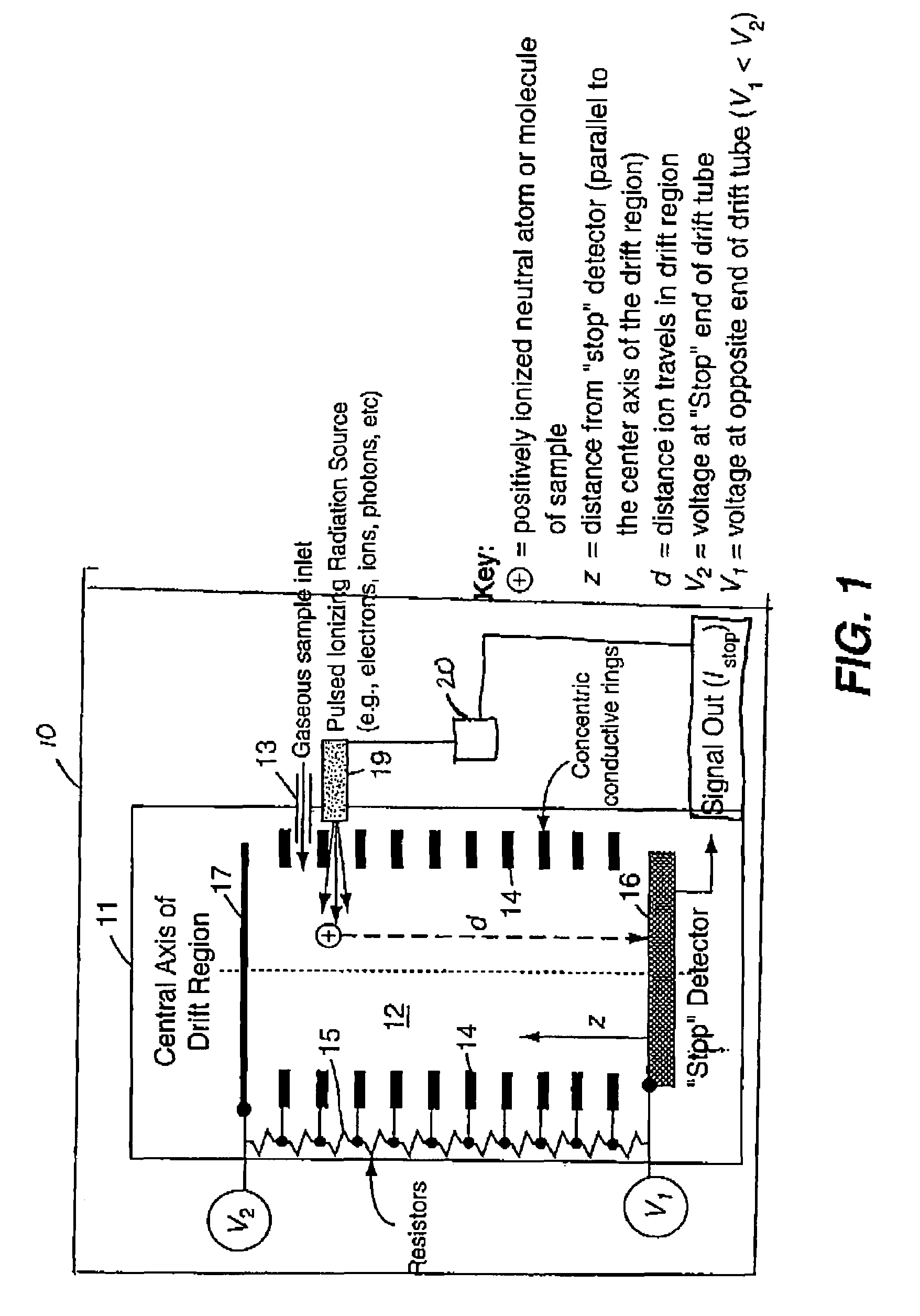
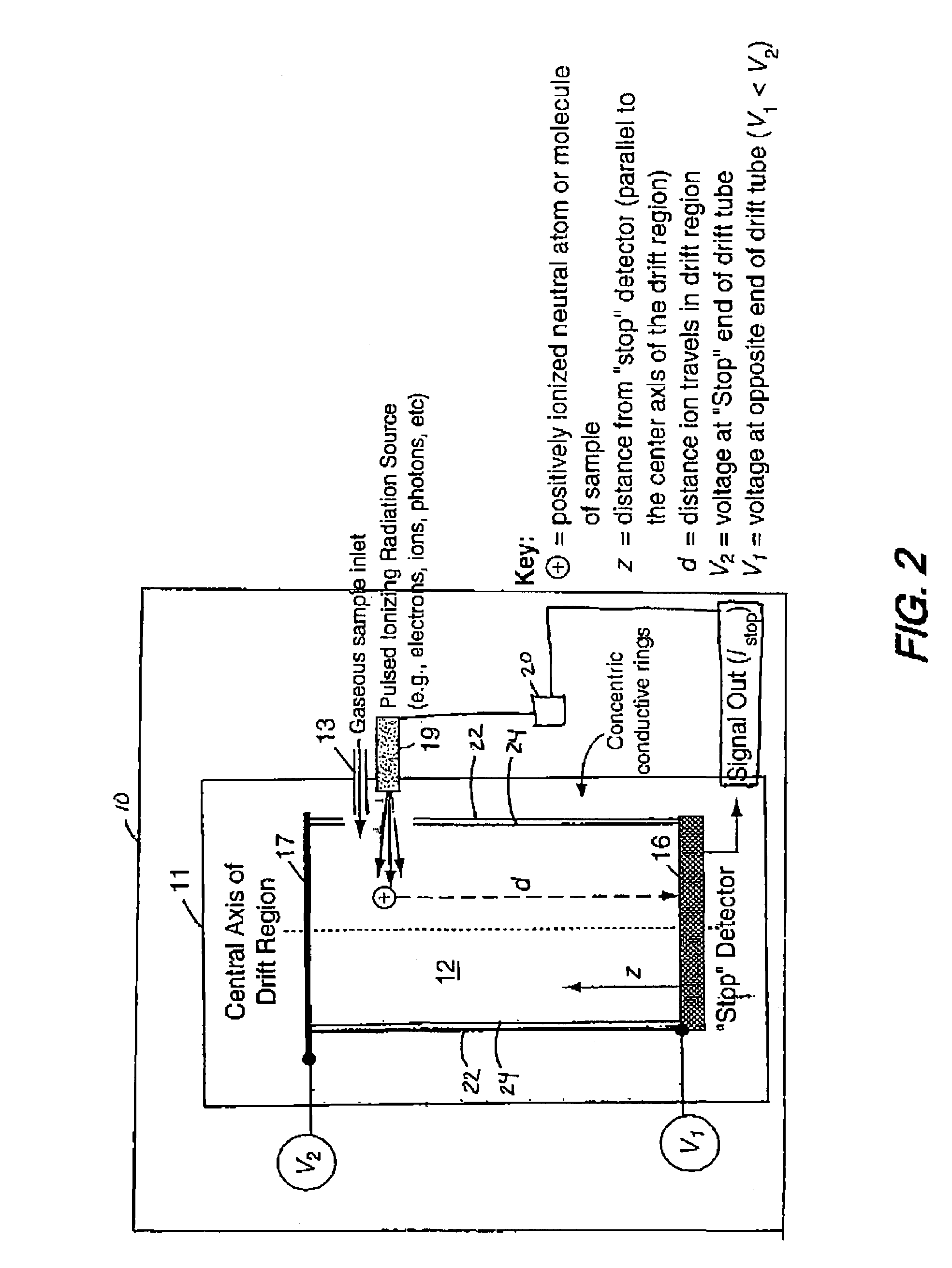
[0021]The present invention ionizes a sample atom or molecule within a drift region having a linear electric field. The electric field accelerates the ions toward a detector, such that the time-of-flight of an ion, from the time of its ionization to the time of its detection, is independent of the distance the ion travels in the drift region. The invention provides high mass resolving power, smaller resource requirements in such areas as mass, power, volume, and pumping capacity, and elimination of the prior art requirement that the location of an ion at time t1 must be known in order to measure its time-of-flight in the drift region. The invention can be understood more easily through reference to the drawing.

[0022]Referring to FIG. 1, there can be seen the time-of-flight mass spectrometer 10 of the present invention resides inside evacuated chamber 11. The gaseous sample to be investigated is introduced into drift region 12 by sample inlet 13, where the sample is a gas . Alternati...


PUM


Abstract

A linear electric field ion mass spectrometer having an evacuated enclosure with means for generating a linear electric field located in the evacuated enclosure and means for injecting a sample material into the linear electric field. A source of pulsed ionizing radiation injects ionizing radiation into the linear electric field to ionize atoms or molecules of the sample material, and timing means determine the time elapsed between ionization of atoms or molecules and arrival of an ion out of the ionized atoms or molecules at a predetermined position.

Description

FIELD OF THE INVENTION[0001]The present invention generally relates to mass spectrometers, and, more specifically, relates to a time-of-flight ion mass spectrometer using a linear electric field. This invention was made with Government support under Contract No. W-7405-ENG-36 awarded by the U.S. Department of Energy. The Government has certain rights in the invention.BACKGROUND OF THE INVENTION[0002]Mass spectrometers are used extensively in the scientific community to measure and analyze the chemical compositions of substances. In general, a mass spectrometer is made up of a source of ions that are used to ionize neutral atoms or molecules from a solid, liquid or gaseous substance, a mass analyzer that separates the ions in space or time according to their mass or their mass-per-charge ratio, and a detector. Several variations of mass spectrometers are available, such as magnetic sector mass spectrometers, quadrupole mass spectrometers, and time-of-flight mass spectrometers.[0003]A...

Claims


Application Information

Patent Timeline
Patent Type & Authority Patents(United States)
IPC IPC(8): H01J49/00H01J49/40
CPCH01J49/0422H01J49/40
Inventor FUNSTEN, HERBERT O.FELDMAN, WILLIAM C.
Owner RGT UNIV OF CALIFORNIA
Why Eureka
Try Eureka