
Ordnance control and initiation system and related method

Inactive Publication Date: 2003-08-28
NORTHROP GRUMMAN SYST CORP
View PDF0 Cites 37 Cited by
  • Summary
  • Abstract
  • Description
  • Claims
  • Application Information

AI Technical Summary

Benefits of technology

[0013] Accordingly, an object of the present invention is an ordnance control and initiation system and method that are reliable relative to known systems and methods, and thus which limit or preclude inadvertent ignition of the ordnance.
[0015] It is also an object of the invention to provide an ordnance control and initiation system and method that offer the flexibility to be scalable.

Problems solved by technology

Perhaps the most significant one is the possibility of unintentional activation of the ordnance, e.g., caused by unwanted and unplanned electromagnetic energy or fields, such as electromagnetic interference, lightning, electrostatic discharge, etc.
However, shielding of the electrical system adds production costs and makes testing and installation difficult.
It also adds to system mass.
Another drawback of some known electrical ordnance systems is their requirement for sometimes lengthy and relatively heavy conductor cabling, such as twisted pair cabling, and the associated shielding and harnesses.
Such systems can be disadvantageous, for example, based on their relatively high mass penalties, relatively substantial installation requirements, and high rework difficulty.
Electrical conductors also can be subject to relatively substantial power losses when they run for significant distances.
When this is done with many known systems, it typically requires additional control circuits and cabling.
As a consequence, for example, it is often not feasible or unduly difficult or penalizing to integrate a telemetry system with the ordnance system.
Such systems, however, also may have drawbacks.
For one, the power transmission capacity of optical conduits typically is relatively limited.
Moreover, optical transmission can be subject to substantial energy loss over long distances, particular at relatively high power levels.
For this reason, optical initiation systems are often are not suitable for large vehicles having lengthy optical conduits, optical transmission.
Another drawback in some electro-optic systems involves the potentially substantial amount of cabling or optical conduit runs to couple the controller to the ordnance devices.

Method used


Image

  • Ordnance control and initiation system and related method
  • Ordnance control and initiation system and related method
  • Ordnance control and initiation system and related method

Examples


Embodiment Construction

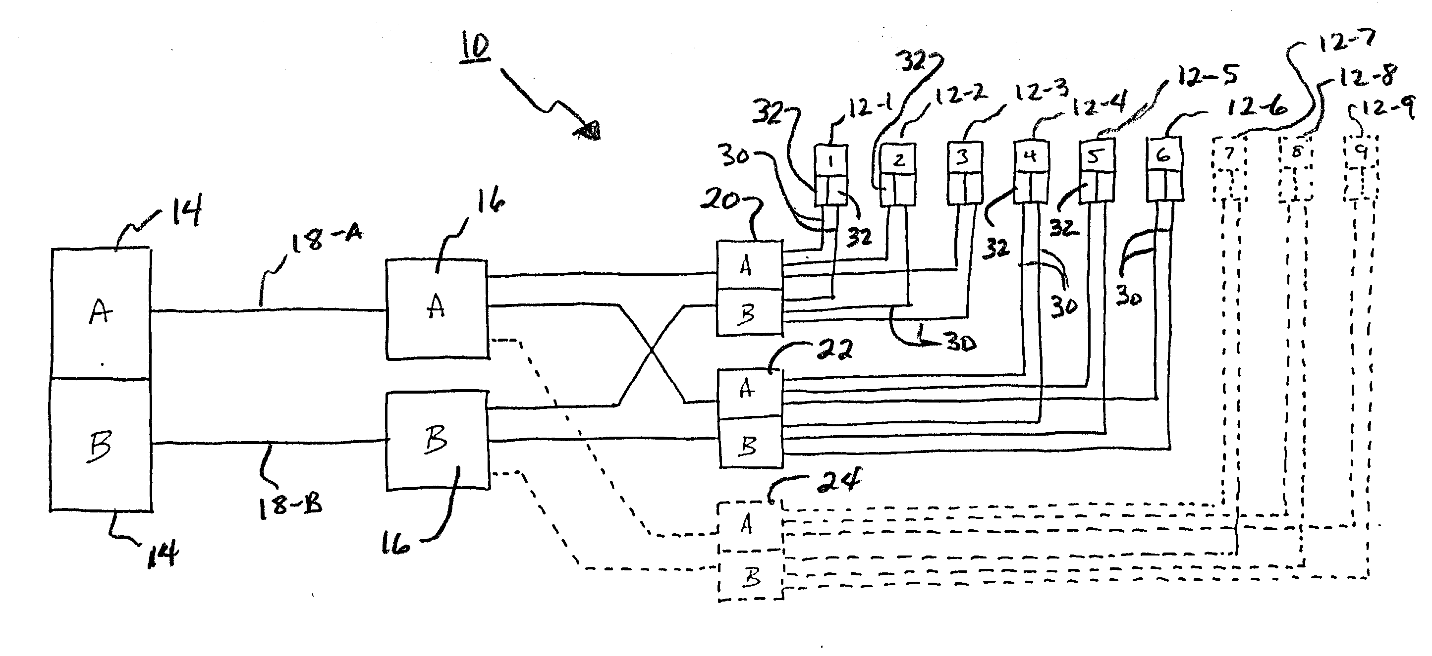
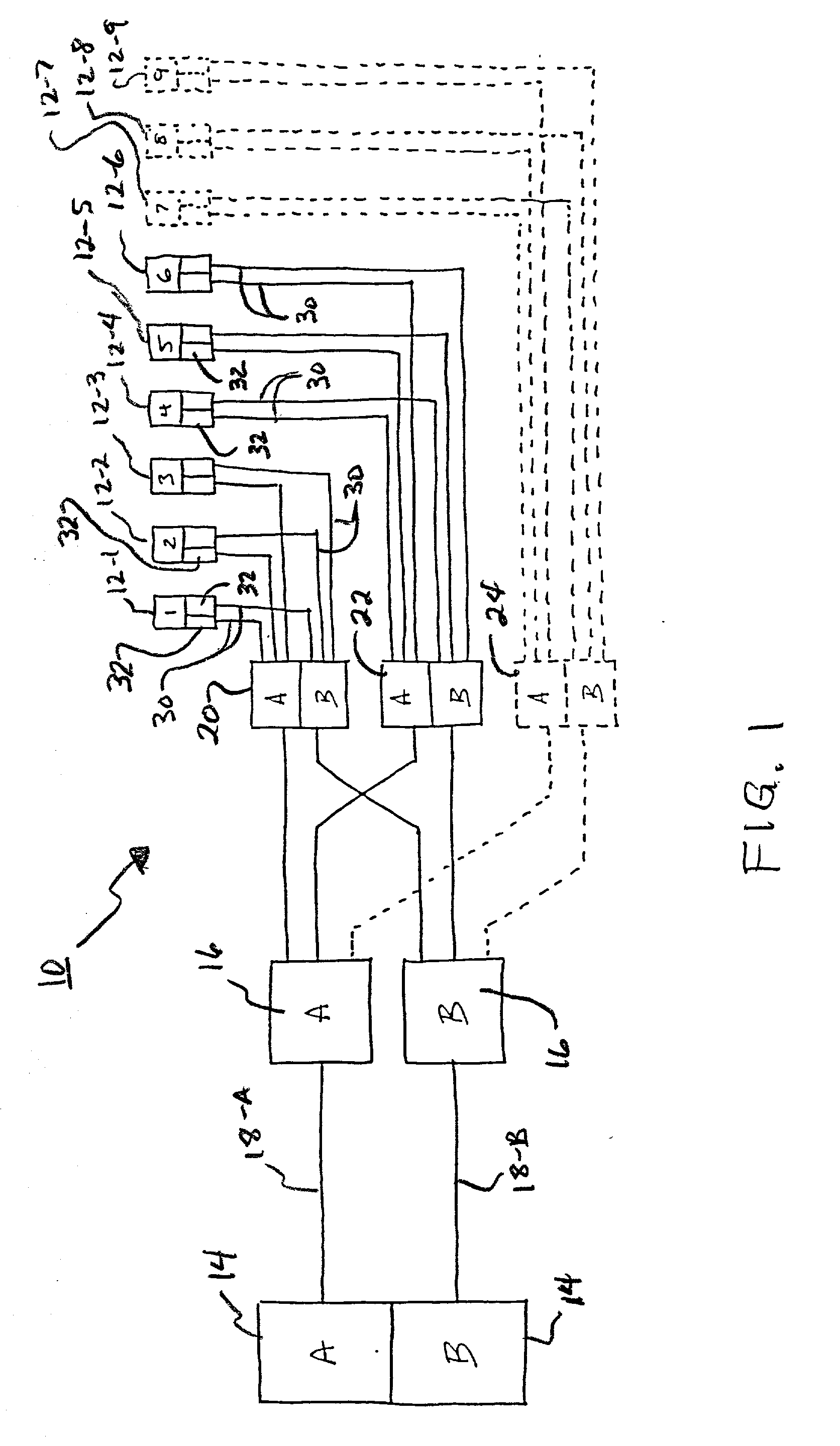
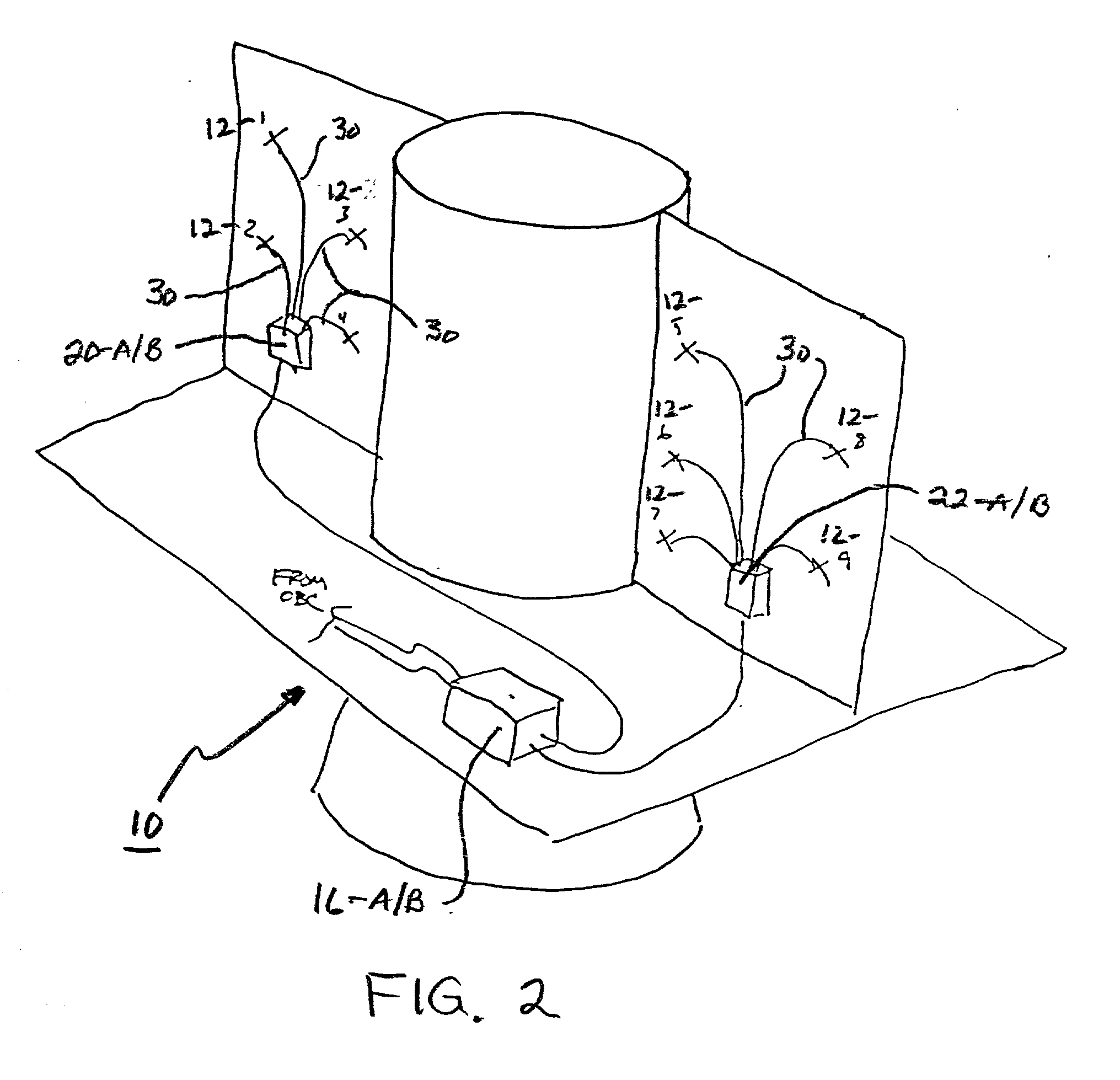
[0035] Reference will now be made in detail to the presently preferred embodiments and methods of the invention as illustrated in the accompanying drawings, in which like reference characters designate like or corresponding parts throughout the drawings. It should be noted, however, that the invention in its broader aspects is not limited to the specific details, representative devices and methods, and illustrative examples shown and described in this section in connection with the preferred embodiments and methods. The invention according to its various aspects is particularly pointed out and distinctly claimed in the attached claims read in view of this specification, and appropriate equivalents.

[0036] It is to be noted that, as used in the specification and the appended claims, the singular forms "a," "an," and "the" include plural referents unless the context clearly dictates otherwise.

[0037] In accordance with one aspect of the invention, an ordnance control and initiation syst...


PUM


Abstract

An ordnance control and initiation system is provided. The system includes a plurality of ordnance devices which may be segregated into a plurality of sets. Each set of the ordnance devices has at least one ordnance device and further includes an ordnance device interface, which preferably includes an optical-to-electrical converter. A controller issues state commands to a master ignition control module operatively coupled to the controller, which re-transmits the state commands to a plurality of slave ignition control modules. Each of the slave ignition control modules associated with one of the sets of the ordnance devices and preferably is optically coupled to each of the ordnance devices within that set. The slave ignition control modules re-transmit the state commands optically to the ordnance devices of the associated the ordnance device set of that slave ignition control module. A capacitive device may be used at the optical-to-electrical converter to store the electrical energy received through the state signal and to selectively discharge that energy into an initiator at the ordnance device to initiate the device. Related devices and methods are disclosed as well.

Description

[0001] 1. Field of the Invention[0002] The present invention relates to an ordnance control and initiation systems and methods useful for managing and controlling the activation of ordnance, for example, such as those used for stage separation in flight vehicles. The system and method, for example, may relate not only to ordnance safing, arming and initiation, but monitoring and telemetry acquisition as well.[0003] 2. Description of the Related Art[0004] There are numerous applications in which it is necessary or desirable to control and / or initiate ordnance with high precision and reliability. One such application, although merely illustrative and not by way of limitation, involves the ordnance associated with rockets, missiles, and similar powered flight vehicles (hereinafter "flight vehicles"). It is not uncommon for such vehicles to include a plurality of ordnance devices for performing interrelated or distinct tasks. By way of example, a flight vehicle may contain multiple stag...

Claims


Application Information

Patent Timeline
IPC IPC(8): F41A19/64F41A19/69F42B15/36F42C11/00F42C19/06F42D1/045
CPCF41A19/64F41A19/69F42D1/045F42C11/00F42C19/06F42B15/36
Inventor RAUSCHER, ROBERT A. JR.
Owner NORTHROP GRUMMAN SYST CORP
Learn More