
Ignition system for an internal combustion engine

a technology of ignition system and internal combustion engine, which is applied in the direction of generator generated ignition energy, induction energy storage installation, other installations, etc., can solve the problems of insufficient combustion of fuel-air mixture, ignition misfiring, and disadvantage that is necessary

Inactive Publication Date: 2003-09-04
ROBERT BOSCH GMBH
View PDF3 Cites 5 Cited by
  • Summary
  • Abstract
  • Description
  • Claims
  • Application Information

AI Technical Summary

Benefits of technology

[0004] The ignition system according to the present invention having the features cited in claim 1 offers the advantage that it is possible in a simple manner to make available high ignition energy, which is adequately proportioned in every operating situation of the internal combustion engine, especially in igniting lean fuel-air mixtures. As a result of the fact that two ignition coils are provided, each of whose secondary winding is connected to one spark plug and whose primary windings can each be acted upon by a switching means using the supply voltage, and that a drive circuit is provided which makes possible a time-displaced driving of the switching means and therefore of the ignition coils, it is advantageously possible to switch on the second ignition coil precisely at the time point at which, in the voltage circuit of the first ignition coil, the switch-off voltage results in the secondary-side generation of the high voltage. In this manner, on the high-voltage side of the second ignition coil, a positive switch-on voltage arises, which is added to the negative spark voltage of the ignition spark generated by the first ignition coil, and therefore the spark voltage present at the ignition electrodes of the spark plug is increased, specifically, more than doubled. In this manner, a greater ignition spark duration and a higher ignition spark current are obtained, resulting generally in making available greater ignition energy. This high ignition energy is well-suited to reliably igniting even lean fuel-air mixtures every time. By connecting in alternating fashion the other ignition coil in the switch-off phase of the previously connected ignition coil, it is possible repeatedly to extend the spark duration over a longer time period.[0005] Preferred embodiments of the present invention are indicated by the other features cited in the subclaims.

Problems solved by technology

If this minimum ignition energy is not made available, the result can be the incomplete combustion of the fuel-air mixture or ignition misfiring.
In this context, however, the disadvantage is met with that is necessary to select a correspondingly large design of an ignition coil.

Method used


Image

  • Ignition system for an internal combustion engine
  • Ignition system for an internal combustion engine
  • Ignition system for an internal combustion engine

Examples


Embodiment Construction

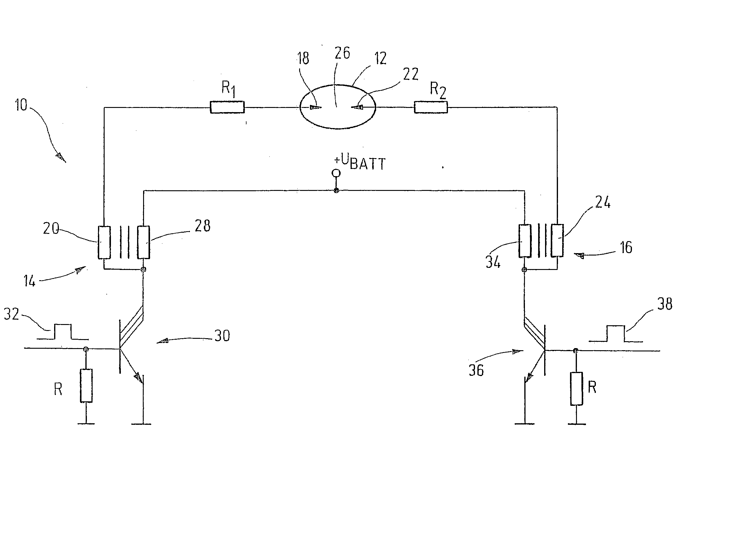
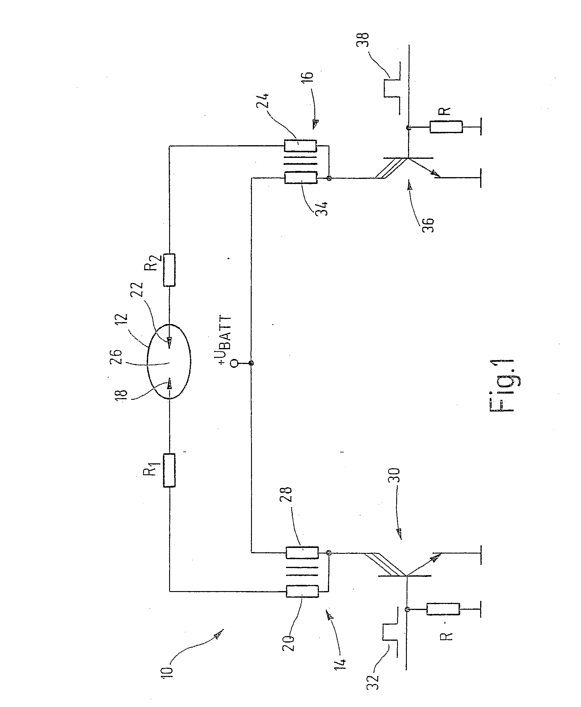
[0010] FIG. 1 depicts an ignition system, designated overall as 10, in a substitute circuit diagram. Ignition system 10 includes a spark plug 12, to which is assigned a first ignition coil 14 and a second ignition coil 16. One electrode 18 of ignition coil 12 is connected to secondary winding 20 of first ignition coil 14. Second electrode 22 of spark plug 12 is connected to secondary coil 24 of second ignition coil 16. Configured between electrodes 18 and 22 is an ignition gap 26. Connected between electrodes 18 and 22, and secondary coils 20 and 24, are resistor R.sub.1 and R.sub.2, respectively. Primary coil 28 of first ignition coil 14 is connected on one side to a supply voltage source U.sub.BATT, in motor vehicles usually the motor vehicle battery. On the other side, primary winding 28 is connected to the secondary winding and a switching means 30. Switching means 30 is a three-phase Darlington transistor. Alternatively, secondary winding 20, via a switch-on suppression diode D...


PUM


Abstract

The present invention relates to an ignition system for an internal combustion engine having an ignition device that requires a high voltage (ignition voltage) for igniting the ignition spark. Two ignition coils (14 and 16) are provided, whose secondary windings (20, 24) are each connected to electrodes (18, 22) of a spark plug (12, 12'), whose primary windings (28, 34) can be connected in each case by a switching means (30, 36) to a supply voltage source, and a drive circuit, via which the ignition coils (14, 16) are driven in a time-displaced manner.

Description

[0001] The present invention relates to an ignition system for an internal combustion engine having the features cited in the preamble of claim 1.BACKGROUND INFORMATION[0002] Ignition systems of the type of the species are known. They act to ignite a compressed fuel-air mixture in the internal combustion engine. For this purpose, using an ignition device, usually a spark plug, an arc discharge is generated between two electrodes of the spark plug. To generate this arc discharge, an ignition voltage in the high-voltage range is made available. To make available this necessary high voltage, it is known to connect the spark plug to the secondary winding of an ignition coil whose primary winding can be connected to a voltage source, which in motor vehicles is usually the motor vehicle battery. In this context, the ignition coil operates as an energy storage device and as a transformer. During the closing time of the primary-side switching means, the electrical energy made available from...

Claims


Application Information

Patent Timeline
Patent Type & Authority Applications(United States)
IPC IPC(8): F02P3/02F02P3/04F02P3/05F02P3/045F02P7/03
CPCF02P3/0435F02P3/02
Inventor MEINDERS, HORSTFEILER, WOLFGANG
Owner ROBERT BOSCH GMBH
Learn More