Method for fabricating a magnetoresistive film and magnetoresistive film

a technology of magnetoresistive film and film, which is applied in the field of method for fabricating magnetoresistive film and magnetoresistive film, can solve the problems of increasing the fabrication process of thin film and reducing the process yield of thin film, and achieves the effect of easily displaying the mr

Inactive Publication Date: 2003-09-11
NAGOYA UNIVERSITY
View PDF5 Cites 3 Cited by
  • Summary
  • Abstract
  • Description
  • Claims
  • Application Information

AI Technical Summary

Benefits of technology

0006] It is an object of the present invention to provide a method for fabricating a new magneto

Problems solved by technology

However, such a junction forming process requires a complicated process, so that the fabricati

Method used


Image

  • Method for fabricating a magnetoresistive film and magnetoresistive film
  • Method for fabricating a magnetoresistive film and magnetoresistive film

Examples


Embodiment Construction

[0027] The present invention will be described concretely on the basis of example, hereinafter.

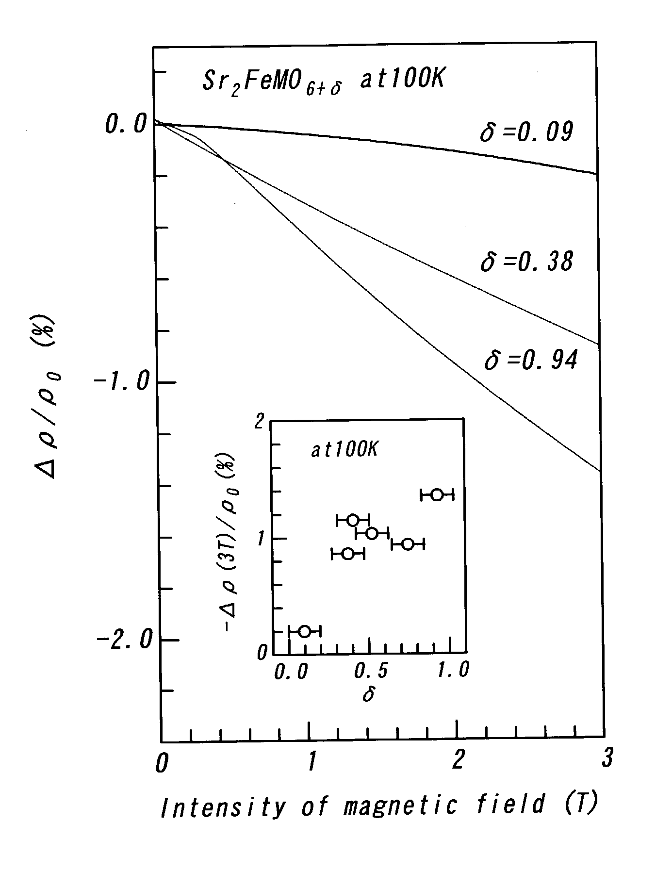
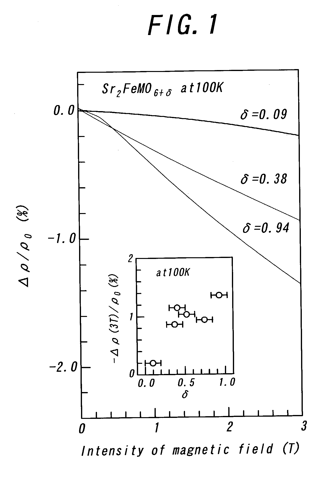
[0028] First of all, a given (100) MgO single crystal was prepared as a substrate, and then, was set in a vacuum pulsed laser evaporation apparatus. Then, the substrate was heated to 700.degree. C. The interior of the apparatus was maintained in a vacuum degree of 1.times.10.sup.-5 Torr or below. Then, an excimer laser beam with a wavelength of 248 nm, a frequency of 5 Hz and a pulse energy of 200 mJ was irradiated onto a Sr.sub.2FeMoO.sub.6 single crystal which was formed by means of melting zone method, to form a Sr.sub.2FeMoO.sub.6 film in a thickness of about 1 .mu.m on the substrate through the evaporation of Sr.sub.2FeMoO.sub.6. The thickness was measured by means of cross sectional SEM observation. For the measurement of electric resistance for the Sr.sub.2FeMoO.sub.6 film, a terminal pattern for four probe measurement was formed on the Sr.sub.2FeMoO.sub.6 film. The distance of the ...


PUM

PropertyMeasurementUnit
Angleaaaaaaaaaa
Temperatureaaaaaaaaaa

Abstract

A double perovskite type oxide film is formed on a given single crystalline substrate. Then, the oxide film in set in an oxygen-including atmosphere, thereby to be oxidized. As a result, oxygen is introduced excessively into the oxide film, to form half metal/insulator/half metal junction and thus, create a MR effect therein.

Description

[0001] 1. Field of the Invention[0002] This invention relates to a method for fabricating a magnetoresistive film and a magnetoresistive film, particularly preferably for a magnetic sensor and a magnetic head.[0003] 2. Description of the prior art[0004] Recently, much attention is paid to a double perovskite type oxide (A.sub.2FeRO.sub.6: A=Sr, Ca, R=Mo, Re), particularly a poly crystalline oxide such as Sr.sub.2FeMoO.sub.6 or Sr.sub.2FeReO.sub.6 because the double perovskite type oxide can exhibit a relatively large magnetoresistive effect (MR effect) at room temperature. It is considered that the MR effect is originated from the tunnel barrier function of adjacent particles in the oxide.[0005] In order to obtain such a MR effect in a thin film, such an attempt has been made as forming half metal / insulator / half metal junction. However, such a junction forming process requires a complicated process, so that the fabricating process for the thin film is increased and the process yield...

Claims


Application Information

Patent Timeline
IPC IPC(8): H01F10/20G01R33/09G11B5/39H01F10/193H01F10/32H01F41/18H01F41/22H01F41/30H01L43/08H01L43/10H01L43/12
CPCB82Y10/00B82Y25/00B82Y40/00G01R33/09G11B5/3903G11B2005/3996Y10T428/1259H01F41/18H01F41/22H01F41/30H01F41/301H01F10/1933Y10T428/32H01F10/1936G11B5/39
Inventor MORITOMO, YUTAKALIU, XIAOJUN
Owner NAGOYA UNIVERSITY
Why Eureka
Try Eureka