Laser -ultrasonic testing system

a technology of ultrasonic testing and laser, which is applied in the field of material testing, can solve the problems of not ensuring that the technique is sufficiently sensitive, material damage, and often only milliwatts at the interferometer level of kilowatt peak power

Inactive Publication Date: 2003-09-18
NAT RES COUNCIL OF CANADA
View PDF9 Cites 8 Cited by
  • Summary
  • Abstract
  • Description
  • Claims
  • Application Information

AI Technical Summary

Problems solved by technology

This has the disadvantage of causing some material damage.
In spite of these advances in speckle insensitive demodulation that make optical detection of ultrasound more practical for detection off industrial surfaces that are usually rough, they do not ensure that the technique is sufficiently sensitive, particularly when the ultrasonic signals are very weak (e.g. thick specimens and ultrasonically absorbing objects), when the surface is strongly absorbing light (e.g. all black carbon-epoxy composite materials) and when detection has to be performed meters away (e.g. objects at elevated temperature and inspection over large aircraft parts).
Kilowatts peak power often gives only milliwatts at the interferometer level because of the many losses encountered when going from the laser to the demodulator.
Such a power would be in practice hardly feasible if needed continuously; fortunately, it is only required from time to time at the repetition rate of ultrasound generation and over a time window in the range of 1 .mu.s to a few 100 .mu.s, depending upon the propagating time of ultrasound in the object or at its surface.
It is readily apparent that these existing detection laser systems are very complex, have a very large footprint and in turn have a high cost, which limits widespread use of the laser-ultrasonic technique.
Long pulse lasers that provide the desired peak power with a pulse duration in the 100 .mu.s range are known to be very noisy and are typically affected by strong relaxation oscillations and even spiking.

Method used


Image

  • Laser -ultrasonic testing system
  • Laser -ultrasonic testing system
  • Laser -ultrasonic testing system

Examples


first embodiment

[0028] this invention is shown in FIG. 4. This embodiment is composed of a long pulse laser oscillator 10 and a two-wave mixing phase demodulator 12. The cavity of the laser oscillator is composed of a mirror 14, an output coupler 16 and a laser head 18, which contains the lasing medium and intra-cavity elements. The laser medium is preferably a solid-state laser medium, such as Nd-YAG, but gas or liquid can also be used. The solid-state laser medium has the shape of a rod, a disk or a slab, and is pumped by a flashlamp or laser diodes (the pumping means is not represented in FIG. 4).

[0029] A diaphragm 20 is inserted in the laser cavity to select the fundamental T.sub.00 laser cavity mode. Two quarter-wave plates, one on each side of the laser medium, are used to reduce the spatial hole burning, resulting in more competition between the modes that could oscillate and higher gain. These two quarter-wave plates also act as a rough mode selector. A glass plate 24 at Brewster angle or a...

third embodiment

[0044] The third embodiment shown in FIG. 10 is obtained by combining two lasers pumped by the same flashlamp. One laser is the detection pulsed laser oscillator as previously described. The second laser 60 is a standard high power, Q-switched laser and is used for the generation of ultrasound. The generation laser cavity is composed of a mirror 62, and output coupler 64, a Q-switch cell 66, a quarter-wave plate 68 and a polarizer 70.

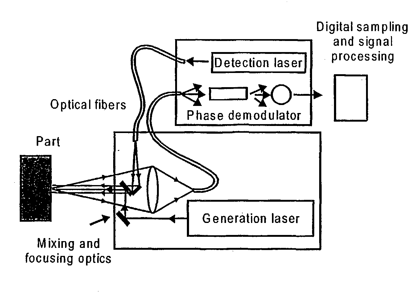
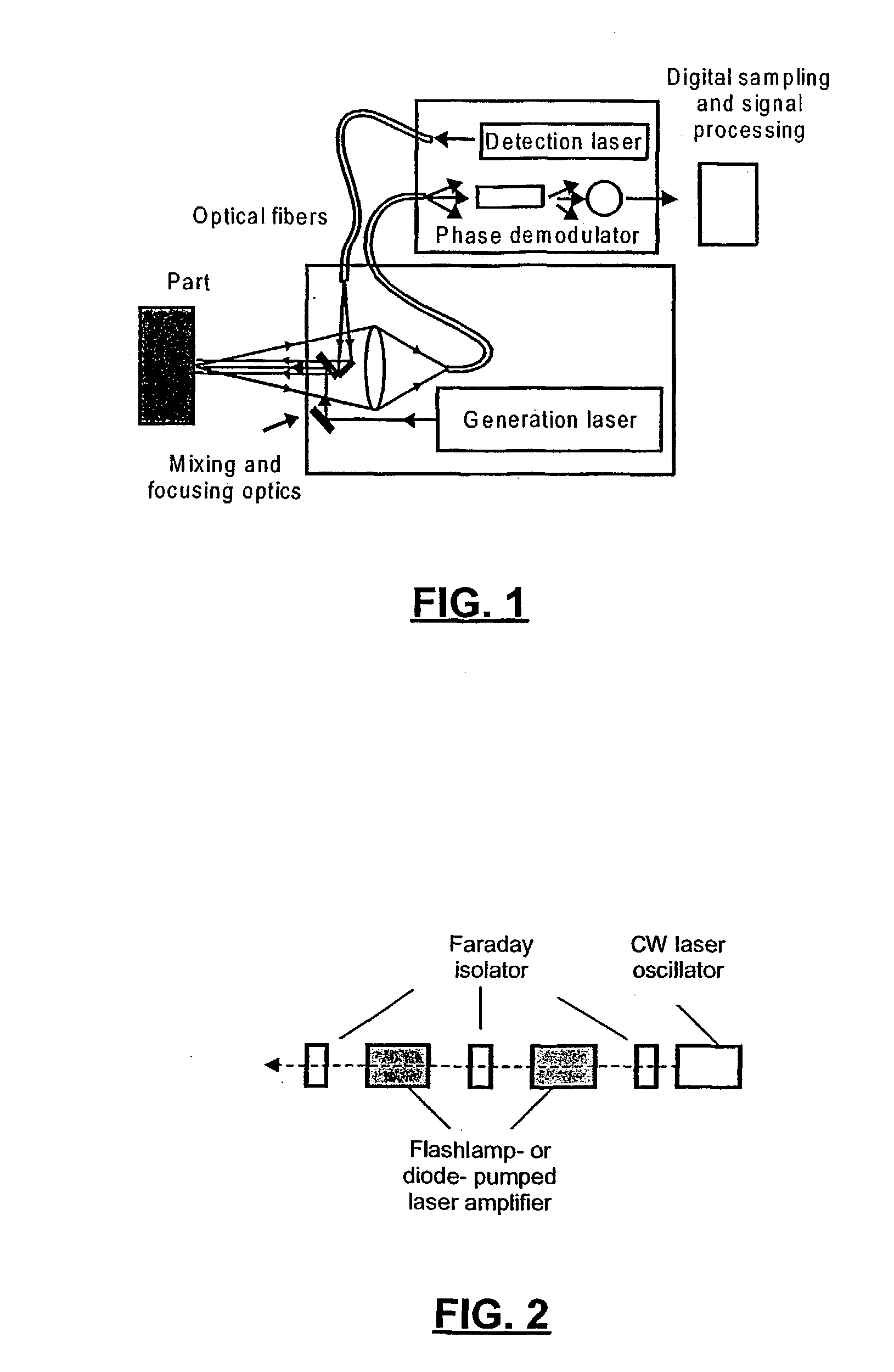
[0045] The output of this laser is sent to the object or workpiece to generate ultrasound that is detected by the detection laser associated with a suitable demodulator such as the two-wave mixing setup described above. The opening of the Q-switch cell is timed in such a way that the time when ultrasound is detected corresponds to the zone where the relaxation oscillations of the detection pulsed laser oscillator have been damped out and noise is minimum. Alternatively, a very simple system can be made by using a single laser slab medium pumped by a fla...


PUM


Abstract

In a method for ultrasonic testing of objects, ultrasound is generated inside or at the surface of the object. The surface of the object is illuminated with a beam from a long-pulse laser oscillator, typically in the range 1 mus to a few 100 mus, that is substantially free of intensity fluctuations. The light from the incident beam that is scattered or reflected by the surface of the object is collected and demodulated to obtain a signal representative of the ultrasonic motion. The method allows for the use of a compact and efficient arrangement.

Description

[0001] 1. Field of the Invention[0002] This invention relates to the field of materials testing, and in particular to a laser-ultrasonic system for the ultrasonic testing of objects or characterizing of materials with ultrasound.[0003] 2. Description of Related Art[0004] Laser-ultrasonics is an emerging technique for the nondestructive evaluation of objects and materials, which has several advantages over other nondestructive techniques. A typical laser-ultrasonic inspection system is composed of two lasers and a phase or frequency demodulator, as shown in FIG. 1. In laser-ultrasonics, the generation of ultrasound is performed at a distance, which in practice can range from a fraction of a meter to several meters. The source of ultrasound is the surface of the material itself and detection of ultrasonic motion is performed off the same surface, which eliminates the coupling liquid and perpendicularity requirements of conventional ultrasonics.[0005] Laser-ultrasonics can be used on p...

Claims


Application Information

Patent Timeline
IPC IPC(8): G01N29/24G01N29/34G01N29/50
CPCG01N29/50G01N2291/015G01N29/348G01N2291/0422G01N29/2418G01N2291/0421
Inventor BLOUIN, ALAINPUJOL, LIONELMONCHAIN, JEAN-PIERRE
Owner NAT RES COUNCIL OF CANADA
Why Eureka
Try Eureka