Pet device

a technology of a pet and a spherical body, which is applied in the field of pet devices, can solve the problems of requiring a long time for measurement, placing an enormous burden on the subject 2, and causing the worst throughput of examination,

Inactive Publication Date: 2003-10-09
HAMAMATSU PHOTONICS KK
View PDF3 Cites 41 Cited by
  • Summary
  • Abstract
  • Description
  • Claims
  • Application Information

AI Technical Summary

Benefits of technology

[0035] The simultaneous radiation and transmission measurement using a PET device is described in an article by C. J. Thompson, et al., entitled "Simultaneous Transmission and Emission Scans in Positron Emission Tomography", IEEE Trans. Nuclear Science, Vol.36, No.1, pp.1011-1016 (1989). This PET device is provided with sub-collimators across a point radiation source in addition to an annular slice ceptor to perform the simultaneous radiation and transmission measurement while the point radiation source in between the sub-collimators is being rotated. However, the PET device described in this article cannot solve the aforementioned problems.
[0037] The present invention was developed to solve the aforementioned problems. It is therefore the object of the present invention to provide a PET device which allows images to be measured in a short period of time and is reconstructed with high accuracy.

Problems solved by technology

However, this time schedule requires the subject 2 to be restrained on a bed in the measurement field of view 1 for the longest time period, thereby placing an enormous burden on the subject 2 and providing the worst throughput of the examination.
Additionally, the subject 2 is easily displacement to be at different positions during each period of time for the transmission measurement and the radiation measurement, thereby causing artifacts to be readily produced.
However, the following problems were present when the two-dimensional simultaneous radiation and transmission measurement was carried out.
Therefore, in response to the limit of the photon detection time resolution of the photon detector, each radiation strength is limited which is emitted from the radio-pharmaceutical injected into the subject 2 and the calibration positron emission radiation. source 3, thereby causing a long period of time to be required for measurement.
The three-dimensional transmission measurement performed with the slice ceptor being retreated from the measurement field of view suffers more seriously not only from the aforementioned problems but also from inaccurate correction for absorption due to intrusion of a large quantity of scattering simultaneous counts into the transmission data.
Therefore, it is substantially impossible to perform the three-dimensional transmission measurement.
However, since this PET device cannot employ the sinogram window method, it is impossible to perform the simultaneous radiation and transmission measurement.
However, the PET device described in this article cannot solve the aforementioned problems.
In this case, insufficiently collimated photons are blocked which have been caused by passing through part of the circumferential direction of the rotating ceptor.

Method used


Image

  • Pet device
  • Pet device
  • Pet device

Examples


first embodiment

[0061] (First Embodiment)

[0062] First, a PET device according to a first embodiment of the present invention is described below.

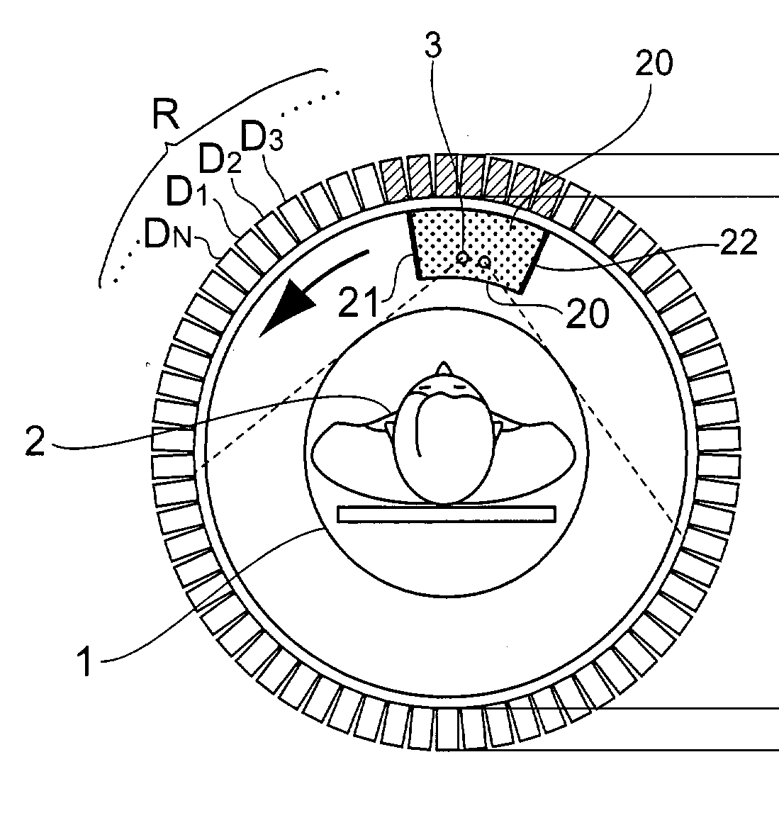
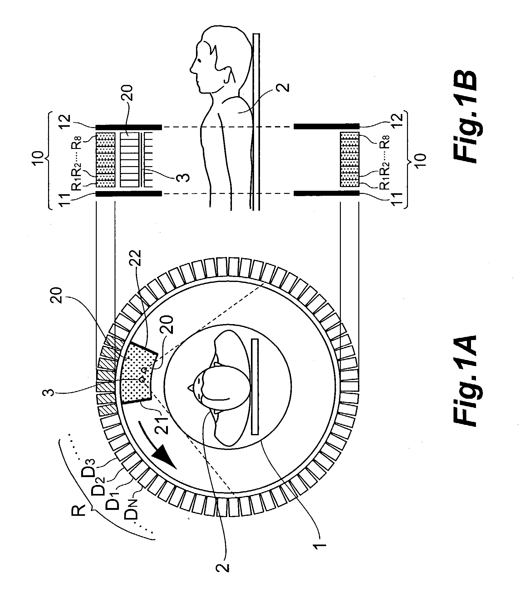
[0063] FIG. 1A and FIG. 1B are explanatory views illustrating the configuration of a detector portion and a rotating ceptor in the PET device according to the first embodiment. FIG. 1A is a view illustrating a detector portion 10 when viewed in a direction parallel to the center axis, FIG. 1B being a cross-sectional view of the detector portion 10 taken along a plane containing the center axis.

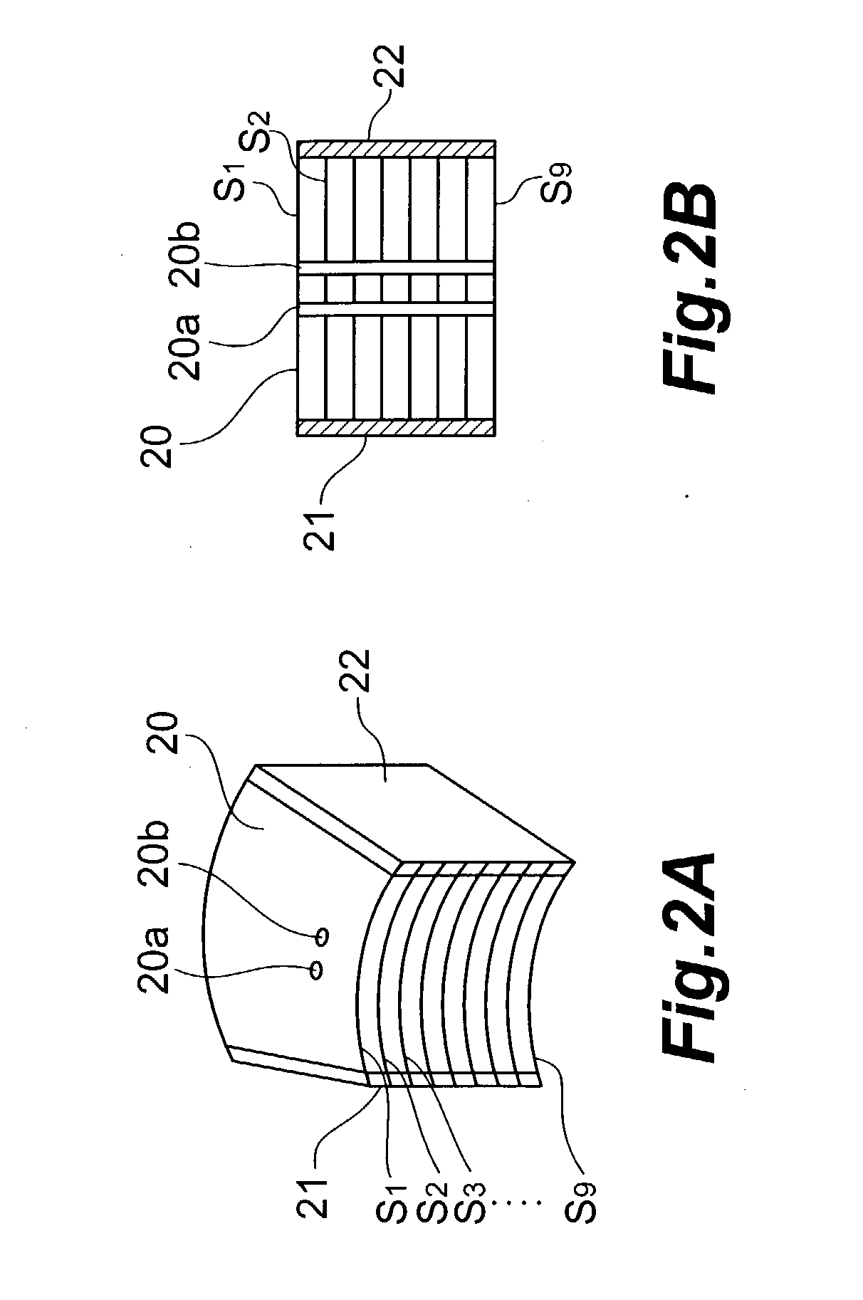
[0064] FIG. 2A and FIG. 2B are more detailed explanatory views illustrating the configuration of the rotating ceptor of the PET device according to the first embodiment, FIG. 2A being a perspective view, FIG. 2B being a cross-sectional view.

[0065] The detector portion 10 comprises detector rings R.sub.1 to R.sub.8 stacked in layers between a shield plate 11 and a shield plate 12. Each of the detector rings R has N photon detectors D.sub.1 to D.sub.N that are annularly...

second embodiment

[0101] (Second Embodiment)

[0102] Now, a PET device according to a second embodiment of the present invention will be described below. FIG. 6A and FIG. 6B are explanatory views illustrating the configuration of the detector portion 10 and the rotating ceptor 20 in a PET device according to the second embodiment. FIG. 6A is a view illustrating the detector portion 10 when viewed in a direction parallel to the center axis, FIG. 6B being a cross-sectional view of the detector portion 10 taken along a plane containing the center axis.

[0103] The PET device according to the second embodiment is different from the one according to the first embodiment in that the second embodiment is provided with the ceptor retract portion 30 having a space for retracting the rotating ceptor 20 therein, and with rotating ceptor retract means for placing the rotating ceptor 20 in the measurement field of view 1 and retracting the rotating ceptor 20 into the ceptor retract portion 30.

[0104] The PET device ac...

third embodiment

[0106] [Third Embodiment]

[0107] Now, a PET device according to a third embodiment of the present invention will be described below. FIG. 7A and FIG. 7B are explanatory views illustrating the configuration of the detector portion 10 and the rotating ceptor 20 in a PET device according to the third embodiment. FIG. 7A is a view illustrating the detector portion 10 when viewed in a direction parallel to the center axis, FIG. 7B being a cross-sectional view of the detector portion 10 taken along a plane containing the center axis.

[0108] The PET device according to the third embodiment is different from the one according to the first embodiment in the following points. That is, the PET device according to the third embodiment is provided with coarse slice collimators 13 to 15 between the shield plate 11 and the shield plate 12 of the detector portion 10, detector rings R.sub.11 to R.sub.18 and a rotating ceptor 20.sub.1 between the shield plate 11 and the slice collimator 13, detector ri...


PUM


Abstract

A rotating ceptor 20 provided inside a detector portion 10 includes nine shield plates S1 to S9 disposed in parallel to each other in between adjacent detector rings R, acts as a collimator, and allows only those photon pairs that have traveled approximately parallel to a slice plane to be made incident upon photon detectors D located behind the rotating ceptor 20. Each of the shield plates S is not formed annularly, and provided near the measurement field of view 1 of part of N photon detectors D that constitute each of the detector rings R. The rotating ceptor 20 is rotatable about its center axis. Each of the shield plates S is provided with bar-shaped radiation source insertion holes 20a and 20b for allowing a bar-shaped positron emission radiation source 3 to be inserted therein and supported thereby.

Description

[0001] 1. Background Art[0002] The present invention relates to a PET device by which the behavior of a tracer labeled by a positron emission radiation source can be imaged.[0003] 2. Description of the Related Art[0004] The PET (Positron Emission Tomography) device detects pairs of 511 keV photons (gamma rays) that occur upon annihilation of electron positron pairs in a living body (subject) having a positron emission radiation source injected therein and then travel in directions opposite to each other, thereby imaging the behavior of the tracer within the subject.[0005] The PET device comprises a detector portion having multiple small photon detectors that are disposed around a measurement field of view in which the subject is placed. The PET device employs a simultaneous counting method to count photon pairs generated upon annihilation of electron positron pairs and accumulates the count (hereinafter referred to as the "radiation measurement"). In accordance with multiple pieces ...

Claims


Application Information

Patent Timeline
Patent Type & Authority Applications(United States)
IPC IPC(8): G01T1/161G01T1/164G01T7/00G21K1/02
CPCG21K1/025
Inventor TANAKA, EIICHIYAMASHITA, TAKAJIOKADA, HIROYUKI
Owner HAMAMATSU PHOTONICS KK
Why Eureka
Try Eureka