Tubular ovality testing

Inactive Publication Date: 2003-10-09
VARCO I P INC
View PDF21 Cites 28 Cited by
  • Summary
  • Abstract
  • Description
  • Claims
  • Application Information

AI Technical Summary

Benefits of technology

0017] The present invention, in certain embodiments, provides a system which processes a sensor generated signal to eliminate the effects of tubular off-centering with respect to the testing equipment. When a tubular to be tested is properly centered with respect to a testing system according to the present invention, and an even number of shoes and sensors are used, the tubular's diameter is a function of the thickness of the shoes and the distances between shoes and corresponding sensor equipment. When a tubula

Problems solved by technology

While manual checking operations may be satisfactory when only random checks are to be made on a lot of oilfield tubulars, this technique can become too expensive and time consuming when numerous axial locations along the length of a tubular are to be checked for outer diameter and ovality conformance.
In some cases manual checking of oilfield tubular diameter and ovality is not practical.
With certain prior art systems some problems remain; e.g. with some existing optical testing systems a relatively long time period is required to process data from detectors which sense the presenc

Method used


Image

  • Tubular ovality testing
  • Tubular ovality testing
  • Tubular ovality testing

Examples


Embodiment Construction

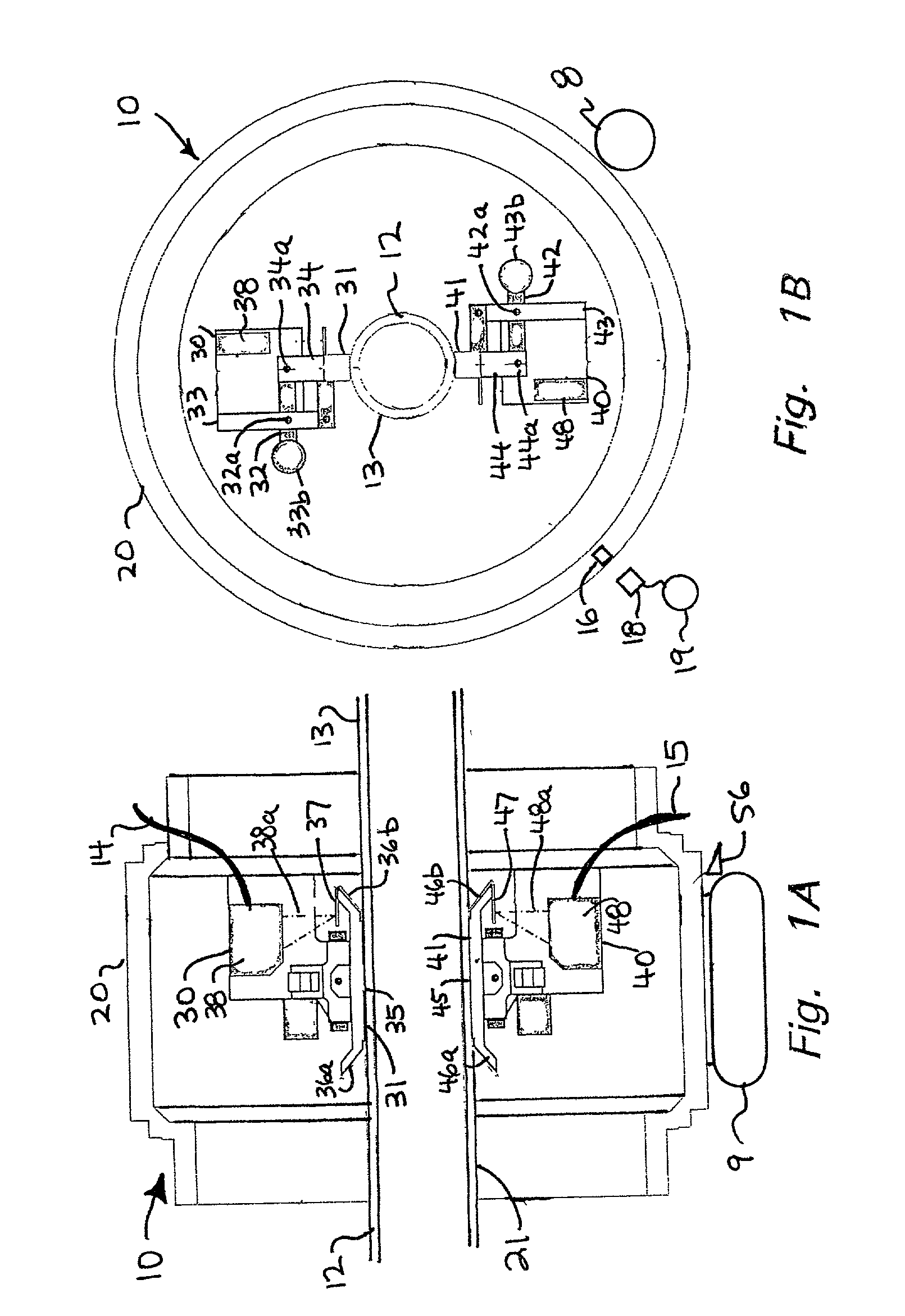
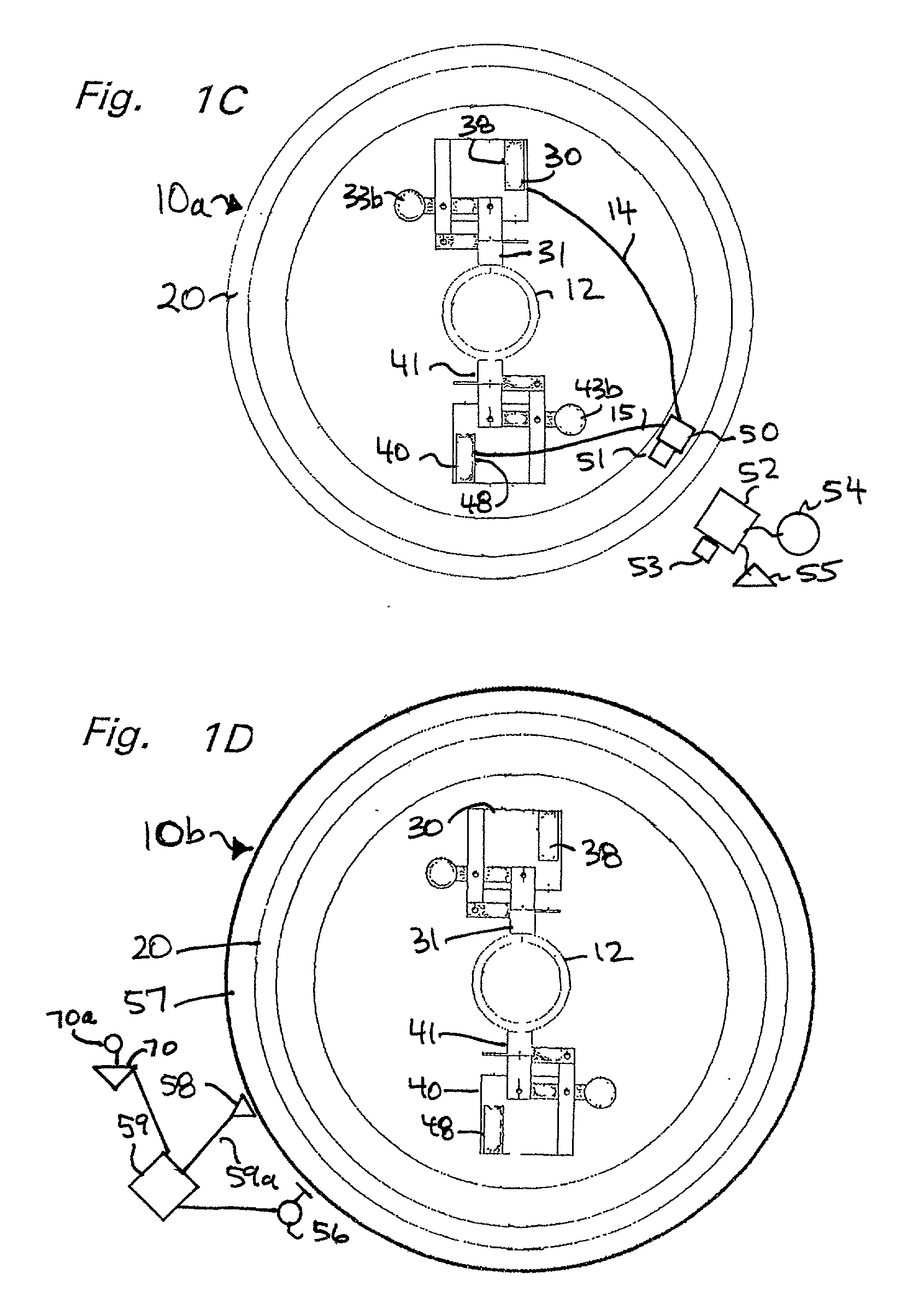
[0030] FIGS. 1A and 1B show schematically a system 10 according to the present invention which has a rotatable head 20 mounted on suitable rotating and movement apparatus 9 (shown schematically; e.g., any known suitable head movement and rotation apparatuses may be used) for rotating the rotatable head 20 around a pipe 12 (or any tubular to be inspected) which is movable through a central opening 21 of the rotatable head 20.

[0031] A pair of sensor devices 30 and 40 are connected to the head 20. The sensor devices 30, 40 each has a detecting shoe 31, 41, respectively, each has an arm 32, 42 which is pivotally mounted at pivot points 32a, 42a, respectively to supports 33, 43. The supports 33, 43 are connected to the head 20. Optionally, a counterweight (or counterweights) 33b, 43b, respectively, may be used with the detecting shoes. Shoe mounts 34, 44 are pivotally mounted to arms 32, 42, respectively, at pivot points 34a, 44a, respectively.

[0032] The detecting shoes 31, 41 are positi...


PUM


Abstract

A system for measuring diameter (inner and/or outer) of a tubular, the system in at least certain aspects including at least one linear distance measuring device with respect to which a tubular to be measured is movable, the at least one linear distance measuring device including a detector for detecting a surface of the tubular, the detector movably mounted to mount apparatus, the detector movable longitudinally along the surface of the tubular and movable axially in response to variation in diameter of the tubular, a rotatable head rotatable with respect to the tubular either outside of it or within it, the mount apparatus secured to the rotatable head, at least one signal production apparatus secured to the mount apparatus or head, and in communication with the linear distance measuring device, the at least one signal production apparatus for producing a signal indicative of distance between said detector and a known point, and transmitting apparatus for transmitting said signals to processing equipment for determining diameter of the tubular; and in certain aspects the linear distance measuring device is a laser device, electronic measurement device, acoustic measurement device, infrared measurement device, or linear variable differential transformer device.

Description

[0001] 1. Field Of The Invention[0002] The present invention is directed to apparatus and methods for measuring the diameter and ovality of tubulars e.g., but not limited to, pipe, tubing, risers, and casing. In certain particular aspects, this invention relates to techniques and systems for detecting irregularities in either the diameter (inner and / or outer) or the ovality of oilfield tubulars by non-destructive testing equipment.[0003] 2. Description of Related Art[0004] The prior art reveals a variety of non-destructive testing equipment to measure ovality of tubulars and to detect material defects in them. Ultrasonic and electromagnetic testing techniques and equipment can detect material defects at rates in the range of from 40 to 400 thirty-foot joints of pipe per hour. Relatively high speed testing equipment reduces the cost of non-destructive testing and reduces the lead time between a pipe order to an inspection yard and the delivery of inspected oilfield tubulars to a well...

Claims


Application Information

Patent Timeline
IPC IPC(8): G01B11/10
CPCG01B11/105G01B11/08
Inventor LAM, CLIVE CHEMOWORMS, MANFRED HERMANNKNAPWOST, HELMUT WOLFGANGDOBBERSTEIN, BERND HELMUT
Owner VARCO I P INC
Why Eureka
Try Eureka