Articulated concrete joint member

a joint member and concrete technology, applied in the direction of roads, paving details, roads, etc., can solve the problems of increasing the height or the lower of one peripheral edge, and eventually cracking of the unitary slab. , to achieve the effect of controlling the cracking of the slab

Inactive Publication Date: 2003-10-09
GALLAGHER STEPHEN JAMES
View PDF12 Cites 4 Cited by
  • Summary
  • Abstract
  • Description
  • Claims
  • Application Information

AI Technical Summary

Benefits of technology

0033] Preferably the articulation members may further include crack propagation means. Said propagation means are intended to assist in the controlled cracking of the slab by providing a line of weakness in the cast in place pavement. Thus, as an alternative to a line of weakness being trowelled into the surface of the concrete, the articulation member having a crack propagation means may provide the same or similar function and advantageously avoid the secondary process of placing these lines of weakness. Alternatively, said crack propagation means may further assist in defining the line of weakness when used with a trowelled surface.
0034] More preferably, the crack propagation means may be projections directed away from the resilient core towards the upper and / or lower surface of the concrete, but not penetrating. Thus the thickness of concrete between the surfaces and the articulation member will be considerably less than that of the surrounding concrete, and thus on application of an interfering factor, the concrete will crack precisely at the required line of weakness and ensure the efficient functioning of the present invention. Preferably the articulation means may further include separation means. The separation means may be projections from the resilient core to the upper and / or lower surface of the concrete and actually penetrating said surface. As an alternative to the crack propagation means, the separation means may be projections that provide a dividing barrier between adjacent portions of the pavement, and thus may separate the pavement into discrete slabs at the time of pouring rather than as a result of cracking. In essence, the separation means may be considered transverse formwork which is conveniently placed at the same time as the articulation member. In addition to the advantages of controlling the cracking of the pavement and clearly defining adjacent slabs, the separation means may further act as a contraction joint between the slabs. Thus the articulation member may provide the multiple functions of articulating the slabs, providing contraction joints to limit gaps in the pavement caused as a result of concrete shrinkage and act as expansion joints to accommodate thermal expansion.

Problems solved by technology

As the pavement is cast in a unitary mass it is recognized that the unitary slab will eventually crack as a result of external factors and the lack of reinforcement.
Unfortunately, following the initial crack at the line of weakness the interfering factor, be it soil or a tree root, will continue to affect the slab.
Further, as such interfering factors inevitably cause differential movement, in that adjacent slabs will be affected to varying degrees, the movement of one slab compared to an adjacent slab will be at a different rate and displacement.
The differential movement of one slab to the next will inevitably cause the raising of one peripheral edge higher or lower than its neighbour.
Such a surface, instead of providing a convenient path for pedestrian vehicles, such as wheelchairs, prams, etc., will instead become effectively impassable for such pedestrian vehicles, not to mention becoming a hazard to foot traffic.
Thus it becomes a serious issue for Municipalities to devote funds from constrained budgets to expensive maintenance programmes to replace the pavements that have suffered differential displacements between the pavement slabs.
Further, such Municipalities must maintain a contingent liability against litigation brought by pedestrians who may injure themselves by tripping and falling as a result of the raised peripheral edges of the slab units.

Method used


Image

  • Articulated concrete joint member
  • Articulated concrete joint member
  • Articulated concrete joint member

Examples


Embodiment Construction

[0035] It will be convenient to further describe the articulation member with respect to the accompanying drawings, which illustrate possible arrangements of the invention. Other arrangements of the articulation member are possible and consequently the particularity of the accompanying drawings is not to be understood as superceding the generality of the preceding description of the invention.

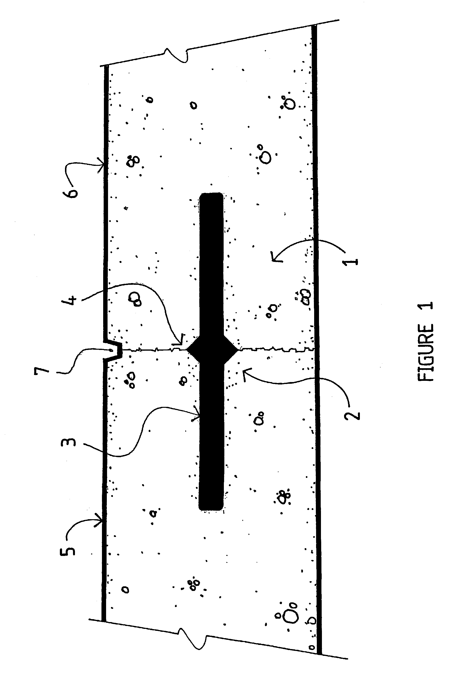
[0036] FIG. 1 is an elevation sectional view of the articulation member, according to the present invention.

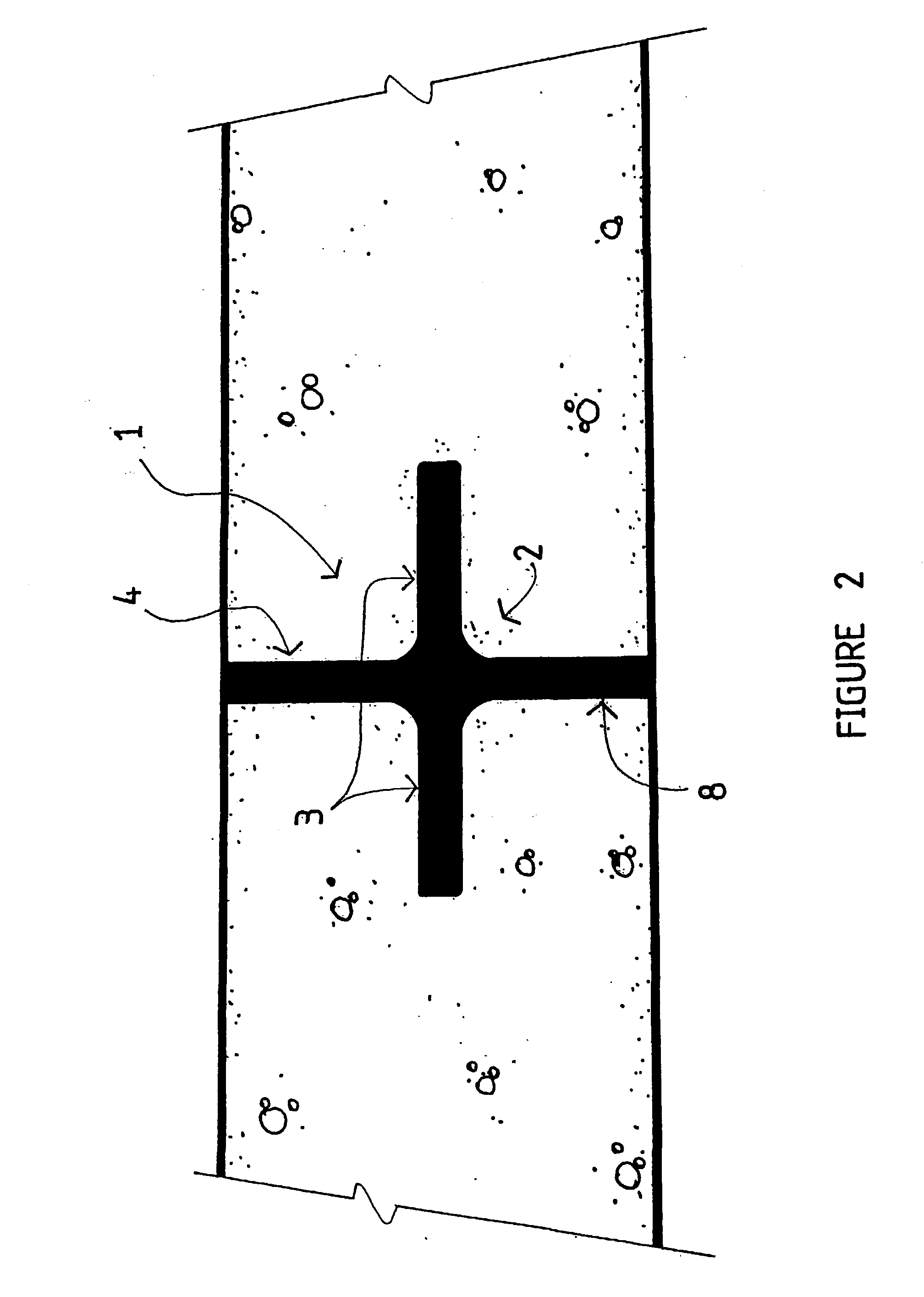
[0037] FIG. 2 is an elevation sectional view of the articulation member, according to another embodiment of the present invention.

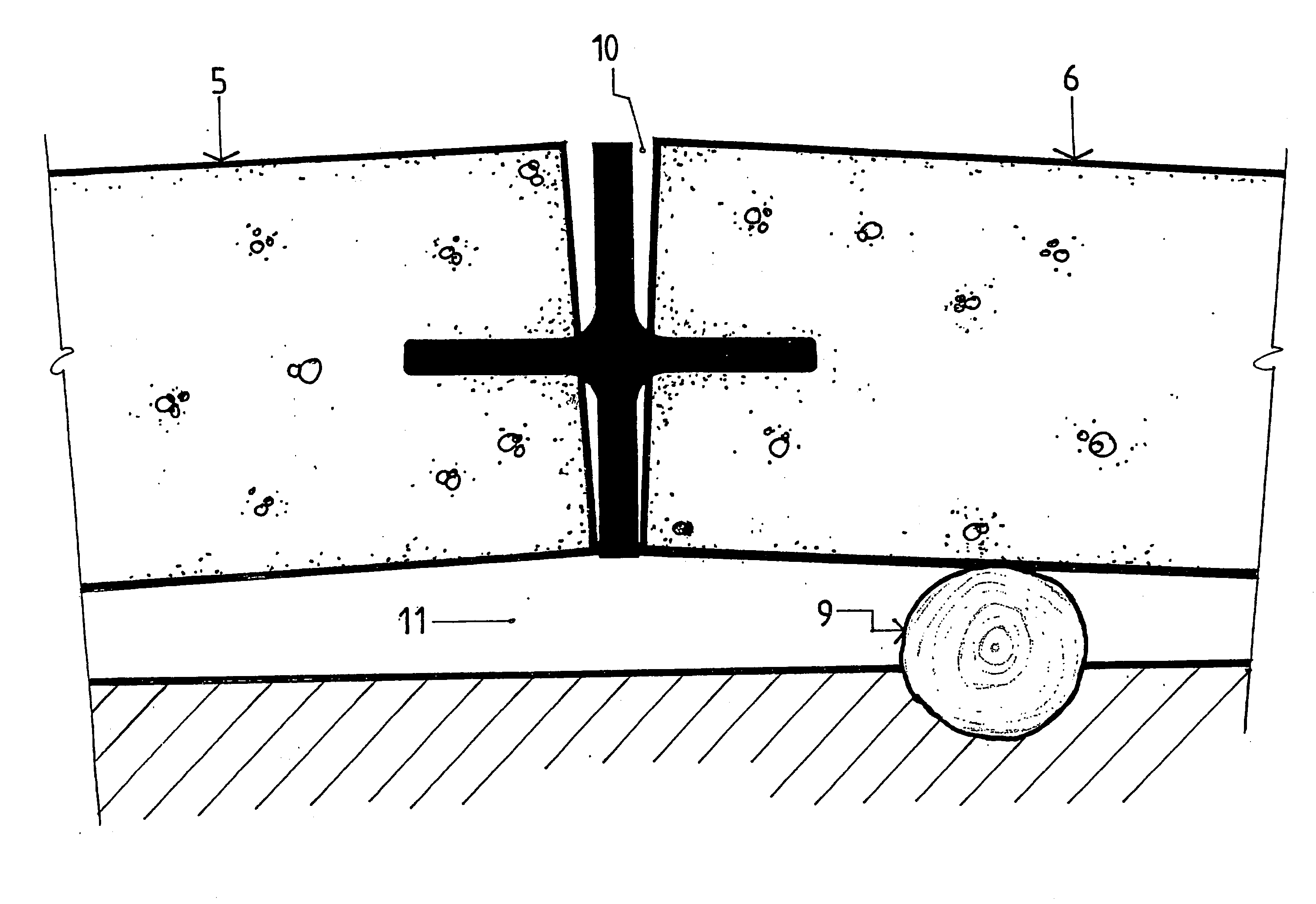
[0038] FIG. 3 is a further elevation sectional view of the articulation member, according to the present invention.

[0039] FIG. 4 is a further elevation sectional view of the articulation member, according to another embodiment of the present invention.

[0040] FIG. 5A is an elevation view of the support means, according to one embodiment of the present invention....


PUM

PropertyMeasurementUnit
specific gravityaaaaaaaaaa
displacementaaaaaaaaaa
resilientaaaaaaaaaa

Abstract

An articulated concrete joint member (1) including a resilient core (2), the core (2) having connections means (3) attached thereto, the connection means (3) adapted to link two co-planar concrete slabs (5, 6) along an adjacent peripheral edge of each slab, wherein on application of an out-of-plane displacement to one of the co-planar concrete slabs (5, 6) the displacement is transmitted to the other slab through pivoting about the articulated joint member (1). In one embodiment, the articulated concrete joint member (1), which further includes crack propagation means (4), is fully immersed in the concrete slab so that the slab is subjected to extraneous loads, the slab cracks along predetermined lines of weakness (7).

Description

[0001] The invention relates to the construction of pavements and concrete slabs, and in particular, the jointing method used in cases of differential movement between said slabs.[0002] Pedestrian thoroughfares whether associated with a road, through a park or other means, and which fall under the control and maintenance responsibility of a Municipal Council will often be formed from concrete. As such pedestrian thoroughfares carry very light traffic loads, typically, such thoroughfares or footpaths will have little or no reinforcement within the concrete.[0003] Typically, the footpath will be formed from pavement slabs which are cast in place in significant lengths so as to economically place the pavement by limiting the number of concrete pours required when constructing the thoroughfare between locations.[0004] As the pavement is cast in a unitary mass it is recognized that the unitary slab will eventually crack as a result of external factors and the lack of reinforcement. Such ...

Claims


Application Information

Patent Timeline
Patent Type & Authority Applications(United States)
IPC IPC(8): E01C11/10E01C11/02
CPCE01C11/106
Inventor MCLEAN, PETER CHARLES
Owner GALLAGHER STEPHEN JAMES
Why Eureka
Try Eureka