Field concentrators for artificial dielectric systems and devices

a field concentrator and dielectric technology, applied in the direction of electrical/magnetic/electromagnetic heating, physical/chemical process catalysts, separation processes, etc., can solve the problems of limited above-effects and the inability of the susceptor's structure to allow the applied energy to penetrate into the entire volume, and achieve the effect of promoting chemical reactions

Inactive Publication Date: 2003-11-13
DALTON ROBERT C
View PDF11 Cites 19 Cited by
  • Summary
  • Abstract
  • Description
  • Claims
  • Application Information

AI Technical Summary

Benefits of technology

0022] This present invention, in its broadest sense, is an improved design that will produce a more homogeneous distribution of energy by 1) the design of the cavity geometry, 2) the location of the applied energy sources, and 3) the depth of penetration of the susceptor. The more homogeneous distribution of energy in the susceptor will

Problems solved by technology

However, these above effects are limited and influenced by the size, shape, conductivity and volume fraction of the material embedded in a matrix of low dielectric loss, low dielectric constan

Method used


Image

  • Field concentrators for artificial dielectric systems and devices
  • Field concentrators for artificial dielectric systems and devices
  • Field concentrators for artificial dielectric systems and devices

Examples


example two

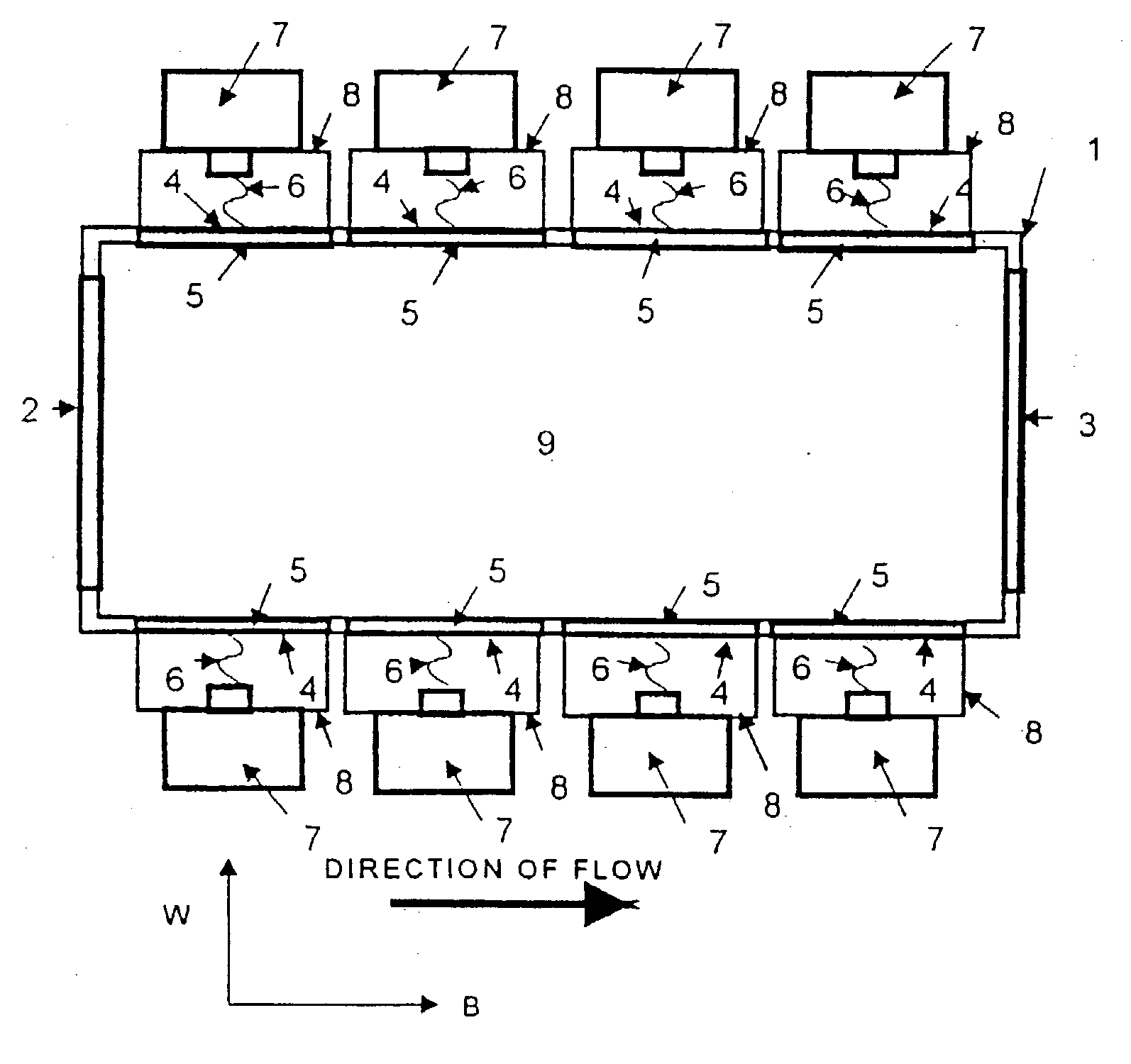
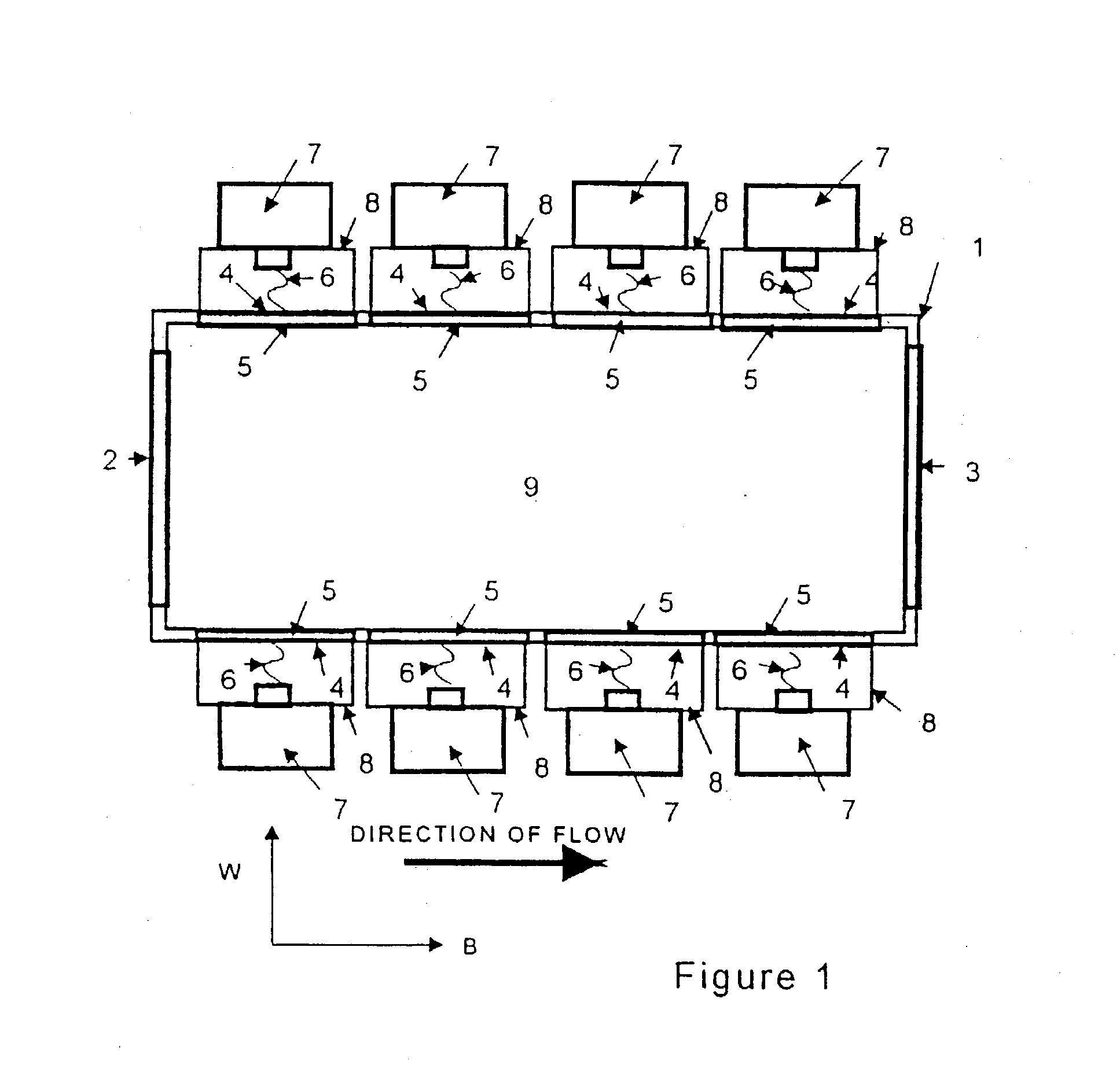
[0026] If interaction of electromagnetic energy with the gaseous species is the primary method for treatment of the gases for chemical reaction or destruction of the pollutants, then to produce volumetric interaction of electromagnetic energy with the gaseous species the applied energy must penetrate the width of interaction inside the cavity at the operating temperature. Therefore, the electromagnetic energy must be able to penetrate the susceptor, and the depth of penetration of the susceptor at the operating temperature must allow for the applied electromagnetic energy to volumetrically interact with the gaseous or particulate species for treatment in the width of interaction. In this method a susceptor may be used to produce turbulence so the gases can mix for better conversion of reactant species to product species.

[0027] For volumetric interaction of electromagnetic energy with the gaseous species, where the shape of the cavity for this device is an irregular-shaped polygon an...

example three

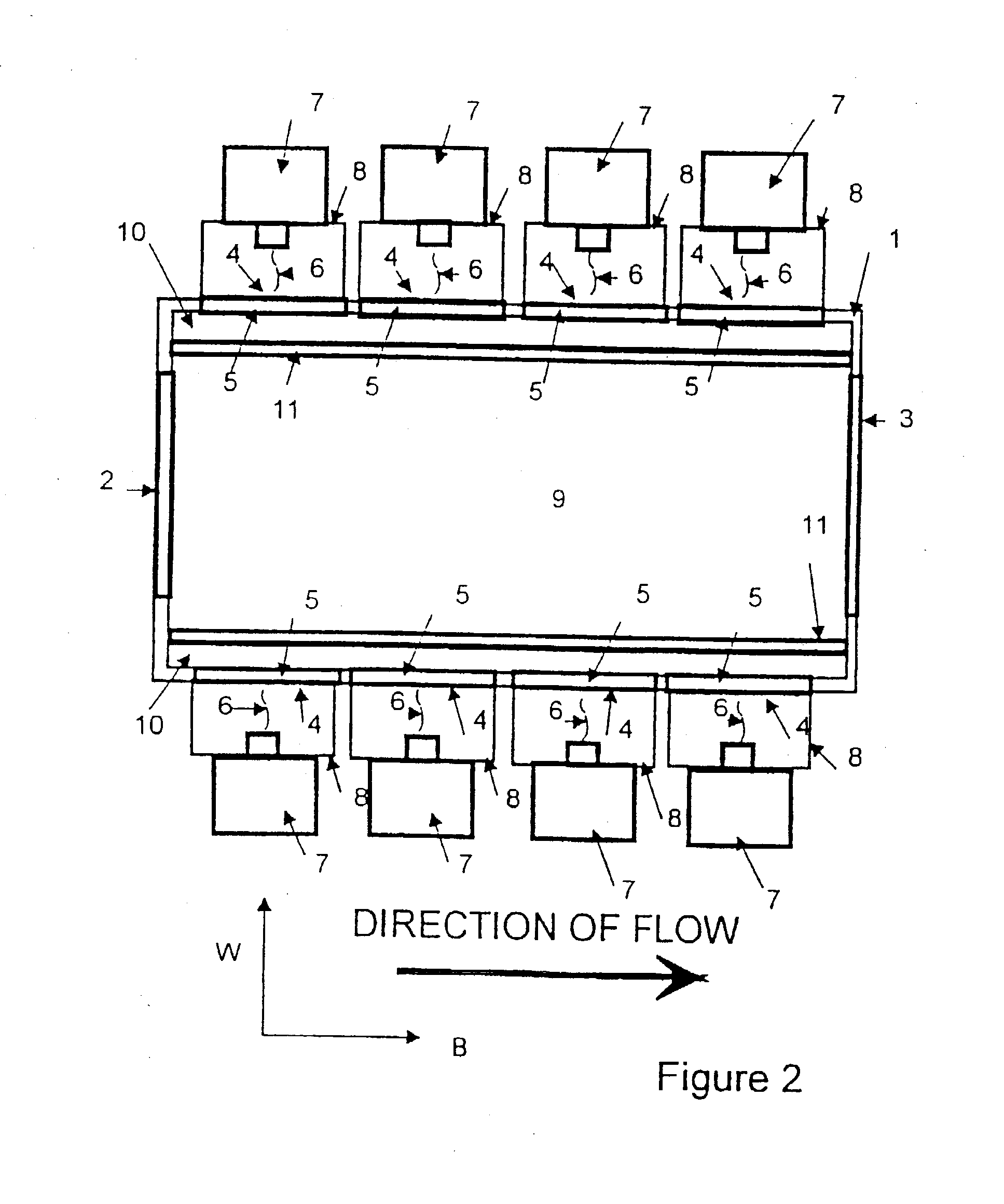
[0031] In example three, the transmission of, absorption of, reflectivity of and scattering of each wavelength of energy that is present in the susceptor becomes important. Instead of the susceptor being constructed of a material, the susceptor may better be constructed of more than one material, which will allow for the wavelength or wavelengths of the applied electromagnetic energy or energies to penetrate and volumetrically interact with the susceptor. And the construction and design of the susceptor and the susceptor's materials of construction will have to be chosen to prevent the design of the susceptor's structure from shielding the wavelength or wavelengths of the applied electromagnetic energy and energies And also, transmission, absorption, reflectivity and scattering properties of the susceptor will be effected by the bulk density of the materials of construction, as well as the porosity size, pore structure and amount porosity in the materials of construction.

[0032] This...

second embodiment

[0289] the method of producing ozone from interaction on an electromagnetic susceptor, comprises the steps of:

[0290] a. providing an electromagnetic susceptor having a matrix material that is nonreflective of electromagnetic energy and that surrounds a non-matrix material that is reflective of electromagnetic energy and that is made from a material that is different from the matrix material, wherein the non-matrix material has exposed surfaces;

[0291] b. controlling the distance between the exposed surfaces of the non-matrix material;

[0292] c. using a matrix material that has a low dielectric losses and low dielectric constant; and

[0293] d. applying electromagnetic energy to the electromagnetic susceptor to produce ozone.


PUM

PropertyMeasurementUnit
Fractionaaaaaaaaaa
Pressureaaaaaaaaaa
Sizeaaaaaaaaaa

Abstract

A method of locally concentrating an applied electric field to promote chemical reaction having a dispersion of individual field concentrators on the surface of a substrate, embedded on a substrate, and embedded on the surface of a substrate, in which the individual field concentrators consists of shaped material and the shape and material are capable of producing a locally concentrated electric field in the vicinity of the field concentrator from interaction between the field concentrator and the applied electric field.

Description

[0001] The present application is a continuation-in-part of U.S. patent application Ser. No. 09 / 897268, filed on Jul. 2, 2001, allowed and which will issue as U.S. Pat. No. 6,512,215 on Jan. 28, 2003, which is a divisional of U.S. patent application Ser. No. 09 / 402240, filed on Sep. 29, 1999, which issued as U.S. Pat. No. 6,271,509 B1 on Aug. 7, 2001, which is the U.S. National Phase under Chapter II of the PCT of PCT Patent Application No. PCT / US98 / 06647, which published as International Publication No. WO 98 / 46046 on Oct. 15, 1998, which claims the benefit of U.S. Provisional Patent Application No. 60 / 041942, filed on Apr. 4, 1997.[0002] 1. Field of Invention[0003] This invention relates to a device and process for thermal treatment of waste gases and reactive gases. The invention is used for the destruction and reduction of pollutants from effluent waste streams, and to produce gaseous products from reactant gases. This invention more specifically relates to a method of locally c...

Claims


Application Information

Patent Timeline
IPC IPC(8): B01D53/32B01D53/88B01J19/02B01J19/08B01J19/12B01J37/02C01B13/10C01B13/11H05B6/72H05B6/80
CPCB01D53/32Y02C20/20B01D2259/80B01J19/02B01J19/087B01J19/12B01J37/0215B01J2219/00141B01J2219/00146B01J2219/00155B01J2219/00159B01J2219/0204B01J2219/0209B01J2219/0218B01J2219/0236B01J2219/0268B01J2219/0286B01J2219/0854B01J2219/0875B01J2219/0892B01J2219/182B01J2219/192C01B13/10C01B13/11C01B2203/0233C01B2203/0238H05B6/6494H05B6/72B01D53/885Y02P20/129Y02P20/141
Inventor DALTON, ROBERT C.
Owner DALTON ROBERT C
Why Eureka
Try Eureka