Optical signal-to-noise monitor having increased coherence

Inactive Publication Date: 2003-11-27
LIGHTHOUSE CAPITAL PARTNERS
View PDF58 Cites 33 Cited by
  • Summary
  • Abstract
  • Description
  • Claims
  • Application Information

AI Technical Summary

Benefits of technology

0060] If the input polarization state 207 is spread by depolarization, then the transformed polarization state 206 is also spread by depolarization, limiting the range of frequencies over which the signal is capable of simultane

Problems solved by technology

The result is that the signal spectra masks the underlying ASE noise level even when the ASE measurement is performed reasonably far away from the center of a given DWDM channel, thereby decreasing the available dynamic range or sensitivity of the OSNR measurement.
The net result is that out-of-band noise measurements--made at the mid-point between adjacent DWDM channels--are typically not sufficiently indicative of the in-band noise levels which actually impact system performance.
A second problem with this methodology is that adjacent DWDM channels may originate at different locations and thereby accumulate different amounts of ASE noise en route to the location of an optical monitor.
Furthermore, the ASE noise component in an optical channel is substantially unpolarized.
However, this method suffers from several disadvantages.
First, polarization scanning using the rotation of waveplates results in a slow temporal measurement of OSNR.
Second, the integrat

Method used


Image

  • Optical signal-to-noise monitor having increased coherence
  • Optical signal-to-noise monitor having increased coherence
  • Optical signal-to-noise monitor having increased coherence

Examples


Example

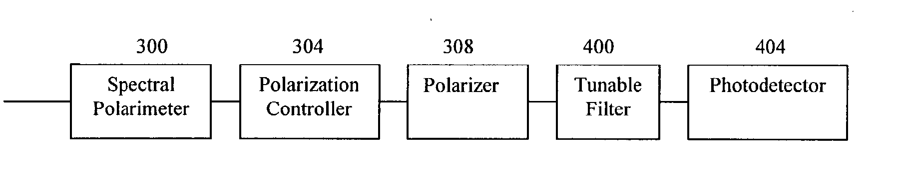
[0061] One embodiment of the OSNR monitor of the current invention--shown in FIG. 3--uses a spectral polarimeter 300, a polarization controller 304, a polarizer 308, a spectral disperser 312, and a detector array 316, arranged in a serial configuration, with each component in optical communication with its neighboring components.

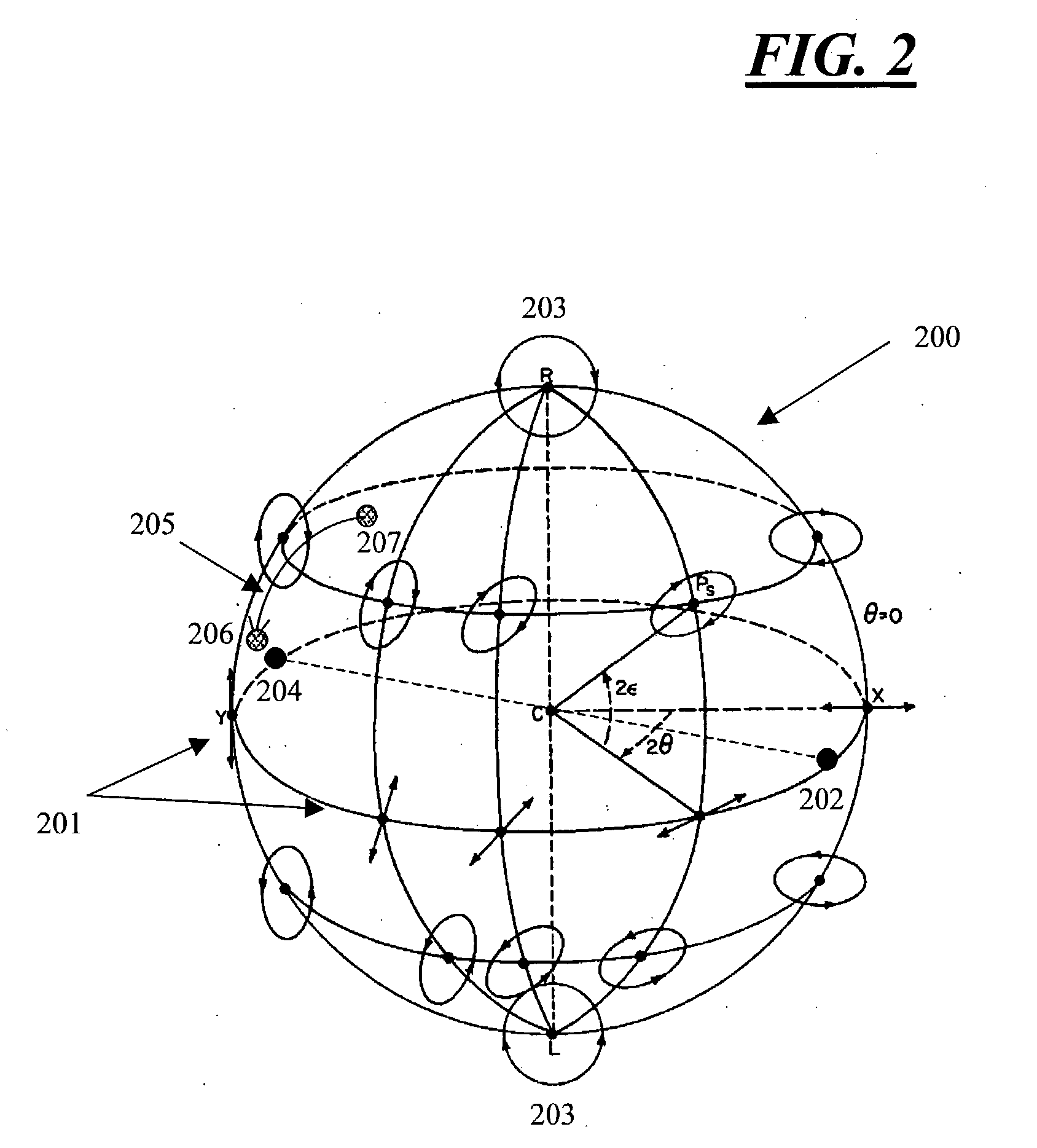
[0062] In operation, the spectral polarimeter 300 measures the polarization state of incident light across a wide spectral band with a spectral resolution narrower than the bandwidth of a single optical channel. After the measurement by the polarimeter 300, the combination of the polarization controller 304 and the polarizer 308 is used to extinguish the signal power component. The polarization controller 304 converts the incident polarization state 207 of each spectral bin measured by the spectral polarimeter 300 to a transformed polarization state 206 nominally orthogonal to the transmission axis of the polarizer 308. The polarizer 308 extinguishes the tra...


PUM


Abstract

Methods and apparatus for rapid, accurate OSNR measurements by directly measuring the spectrally-resolved State of Polarization (SOP) variation across each DWDM channel and using a polarization controller to deterministically extinguish the signal across narrow frequency subbands within each DWDM channel. In-band ASE noise is subsequently measured as a function of frequency across the channel bandwidth.

Description

[0001] CROSS-REFERENCE TO RELATED APPLICATIONS[0002] The present application claims the benefit of co-pending United States provisional application no. 60 / 371,534, filed on Apr. 10, 2002, and assigned to Terapulse, Inc., the entire disclosure of which is incorporated by reference as if set forth in its entirety herein.[0003] The present invention relates to optical measurements, and, in particular, to methods and apparatus for optical signal-to-noise measurements.[0004] The optical signal-to-noise ratio (OSNR) is a direct measure of the quality of signal carried by an optical telecommunications link. The OSNR is the ratio of the power of the signal in the channel to the power of the noise in the channel: 1OSNR = P signal P noise ( Eq . 1 )[0005] The OSNR may provide a very good estimate of the bit-error rate (BER) of the optical link and, as such, a measurement of the OSNR is often important for real-time optical network management at the physical layer.[0006] The OSNR of an optical...

Claims


Application Information

Patent Timeline
IPC IPC(8): H04B10/08
CPCH04B10/07955H04B10/077
Inventor WEIN, STEVEN J.TARGOVE, JAMES D.
Owner LIGHTHOUSE CAPITAL PARTNERS
Why Eureka
Try Eureka