Laser system slag removal

Inactive Publication Date: 2003-12-04
FIRST CALL EXPLOSIVE SOLUTIONS
View PDF0 Cites 41 Cited by
  • Summary
  • Abstract
  • Description
  • Claims
  • Application Information

AI Technical Summary

Benefits of technology

0011] By way of summary, the present invention is directed to a laser deslagging device for the cleaning of boilers. A primary object

Problems solved by technology

These deposits (often referred to as slag) interfere with the transfer of heat energy from the combustion gases to the medium being heated.
This results in deposits which grow rapidly, resist removal, create partial or total blockages in the gas flow paths of the boiler, result in heavy accumulations which may fall and hence cause mechanical damage within the boiler, create boiler inefficiency, and cause corrosion damage due to diffusion of molten or vapor materials into the tubing surfaces.
However, this process is costly, since the boiler must be shut down (i.e. brought off line) in order to perform this type of cleaning.
Thus, valuable production time is thereby lost.
This lost production time includes not only the hours during which the cleaning process is being performed, but also the several hours prior to cleaning when the boiler must be taken off line to cool down, and the several hours subsequent to cleaning for the boiler to

Method used


Image

  • Laser system slag removal
  • Laser system slag removal
  • Laser system slag removal

Examples


Embodiment Construction

[0030] The present invention and the various features and advantageous details thereof are explained more fully with reference to the non-limiting embodiments described in detail in the following description.

[0031] 1. System Overview

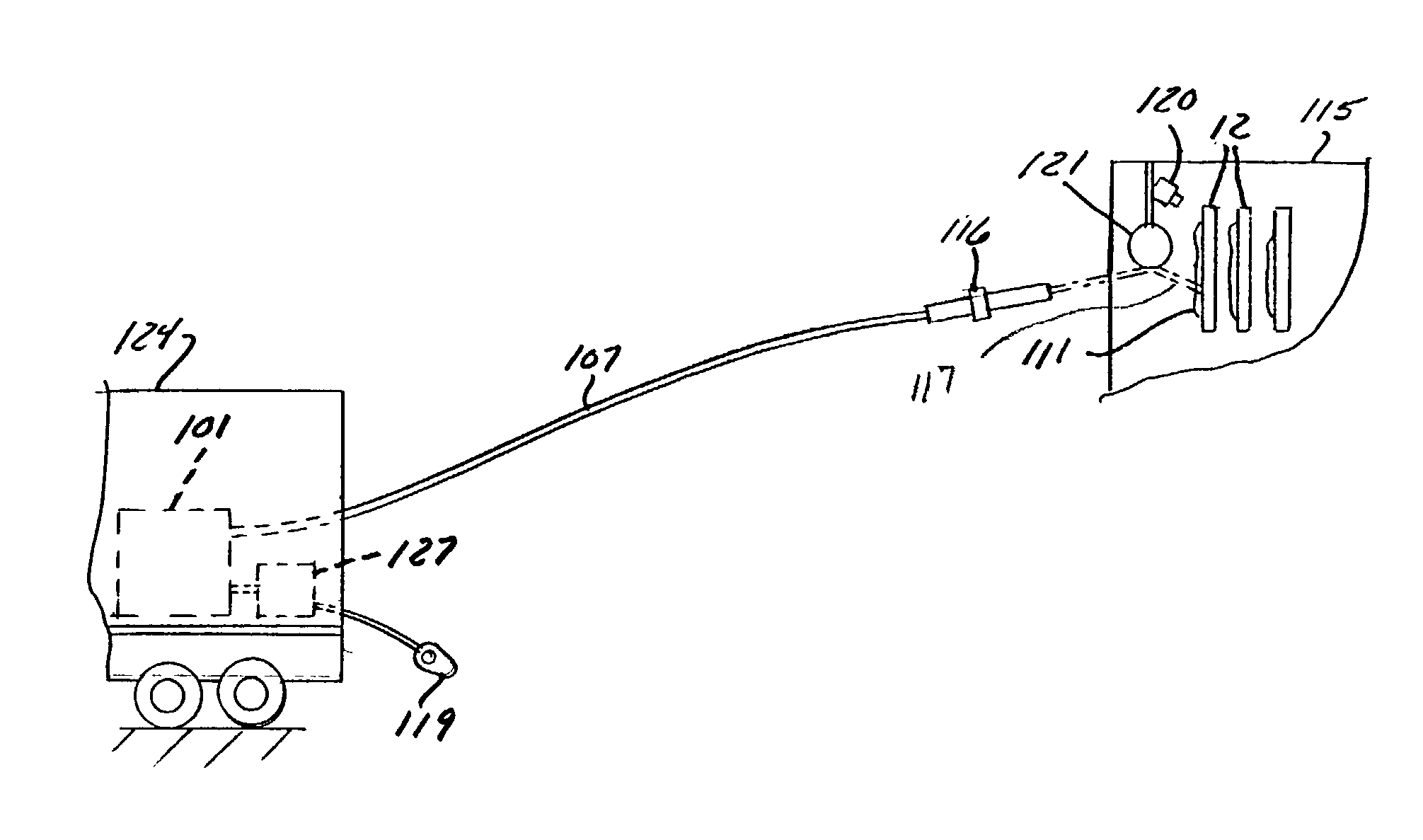
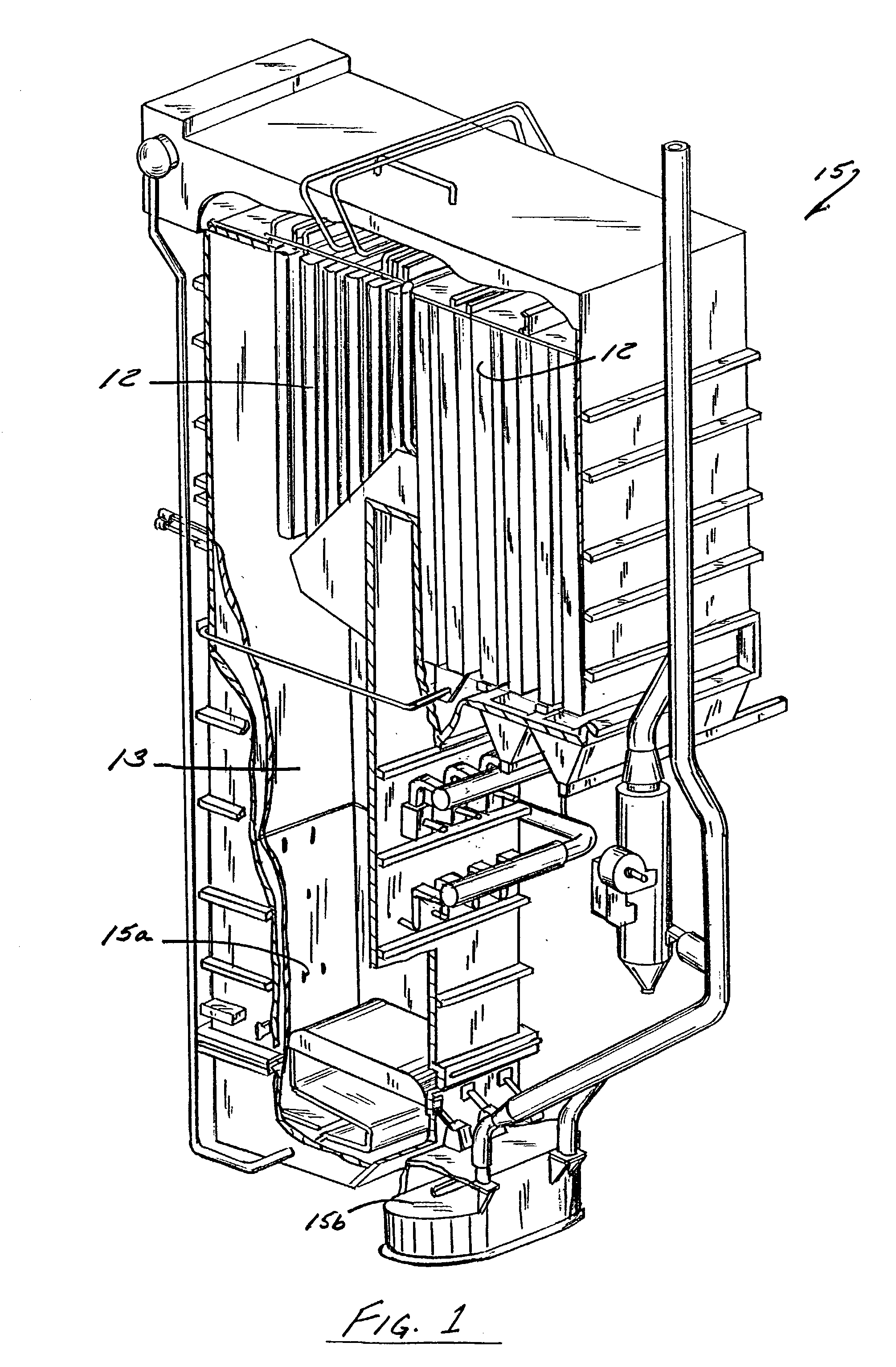
[0032] The present invention comprises a laser deslagging system for cleaning boilers, fireboxes, and slope areas having typical online temperatures between 1900-2500 degrees Fahrenheit. The inventive system is designed to be useful with a variety of boilers. For example, the boiler may be a conventional boiler made of heavy-duty steel plates such as those currently used in the power industry. A firebox and substrate tubes are contained inside the boiler and are generally constructed of steel or stainless steel. The boiler walls preferably have portals to allow for access into the inside of the boiler.

[0033] The laser main unit of the present invention may have many useful features. For example, the laser is preferably constructed to meet the temperature...


PUM

PropertyMeasurementUnit
Thicknessaaaaaaaaaa
Distanceaaaaaaaaaa

Abstract

A system for removing slag from a boiler includes a laser, a targeting system, and a computer system for controlling the operation of the laser and targeting system. Preferably, the laser includes chemicals contained in a mixing pre-chamber. A pump connects to the pre-chamber, and an iodine laser diode connects to the pump. The laser unit also has a power source, cooling system, and a raw beam laser. The targeting system is driven by targeting software and includes an optical targeting system. Preferably, the system also includes a mobile trailer with a computer control room, a main laser operating unit, and a portable optical targeting system connected to the laser unit. Fiber optic cable connects the targeting system and the laser. The online deslagging method includes transporting and setting-up the system, relaying set-up information, feeding targeting information, activating and operating the laser to remove slag from within the boiler.

Description

[0001] 1. Field of the Invention[0002] The present invention relates in general to the field of laser cleaning. More particularly, the present invention relates to particulate removal from the heat exchange and other inner surfaces in a boiler. Specifically, a preferred embodiment of the present invention relates to a laser deslagging device for boilers.[0003] 2. Discussion of the Related Art[0004] Electrical power generating plants commonly employ systems in which boilers are fueled by coal or oil. These in turn produce steam for driving turbines to produce electricity. Typical boilers include, among other components, a furnace evaporator section and various heat exchange units such as superheaters, reheaters, precipitators, fire boxes, slope area, economizers and, air heater sections. A furnace evaporator section is provided with water walls, while the various heat exchange units include tubing for carrying the medium, in the form of water or steam. These are heated, while combust...

Claims


Application Information

Patent Timeline
IPC IPC(8): B08B7/00B08B9/02B23K26/06F28G13/00
CPCB08B7/0042F28G13/00B23K26/0635B08B9/023B23K26/0624
Inventor BROWN, ROBERT K.CAMMARATA, FRANK A. JR.
Owner FIRST CALL EXPLOSIVE SOLUTIONS
Why Eureka
Try Eureka