
Fuel cell performance recovery by cyclic oxidant starvation

a technology of cyclic oxidant and fuel cell, which is applied in the direction of cell components, electrochemical generators, cell component details, etc., can solve the problems of performance decay, reduced output voltage at any given current density, and worse decay rate following such rejuvenation procedures, so as to improve the regeneration of fuel cells the effect of reducing the time required

Inactive Publication Date: 2003-12-04
AUDI AG
View PDF2 Cites 33 Cited by
  • Summary
  • Abstract
  • Description
  • Claims
  • Application Information

AI Technical Summary

Benefits of technology

[0003] Objects of the invention include: improved regeneration of fuel cell performance following long-term decay; reducing the time required to rejuvenate a fuel cell following long-term performance decay; a more effective, long-term fuel cell rejuvenation method; rejuvenation of a fuel cell without causing an increase in the future rate or extent of performance decay; and fuel cell regeneration which can be simply implemented with an uncomplicated control scheme.
[0005] The invention has the surprising result that rates of decay not only do not increase following rejuvenation according to the present invention, but actually decrease, whereby the invention provides a methodology for increasing long-term fuel cell performance.

Problems solved by technology

It is known that operation of PEM (polymer electrolyte membrane) fuel cells for extended periods (several hundred or more hours) results in performance decay; that is, a reduction in output voltage at any given current density.
However, evidence therein suggests that the rate of decay following such rejuvenation procedures is worse, further suggesting that this is not a long-term solution to the performance decay problem.

Method used


Image

  • Fuel cell performance recovery by cyclic oxidant starvation
  • Fuel cell performance recovery by cyclic oxidant starvation
  • Fuel cell performance recovery by cyclic oxidant starvation

Examples


Embodiment Construction

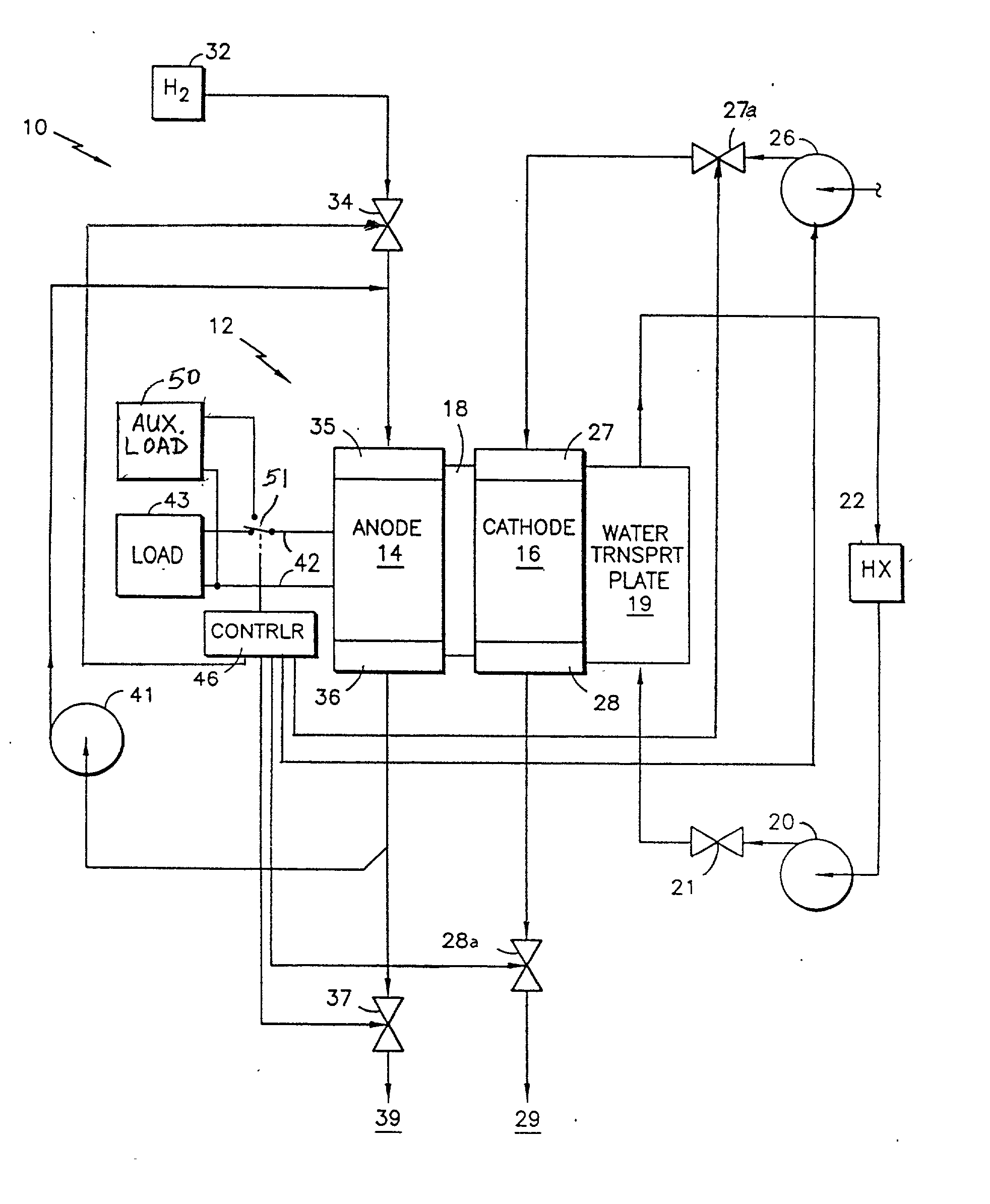
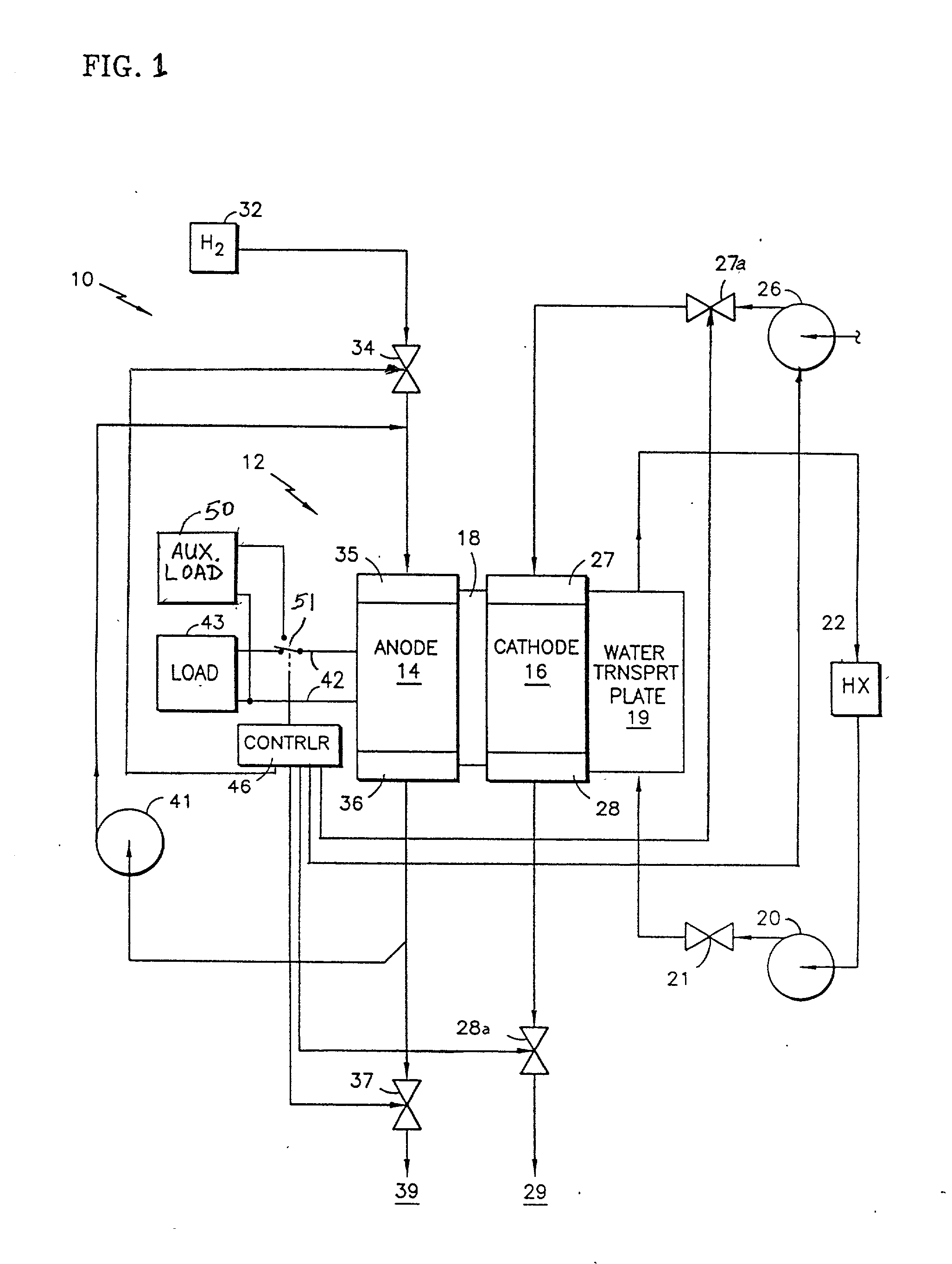
[0013] Referring to FIG. 1, a fuel cell power plant 10 includes a cell stack assembly 12 which comprises a plurality of individual fuel cells stacked together in contiguous relationship, although only a single cell is illustrated in FIG. 1. Each fuel cell 12 includes an anode compartment 14, a cathode compartment 16, and a polymer electrolyte membrane 18. The anode compartment contains an anode and an anode flow field which are not shown. The anode consists of a catalyst adjacent to the polymer electrolyte membrane and a porous support plate all of which are known. The cathode compartment contains a cathode and a cathode flow field which are not shown. The cathode consists of a catalyst adjacent to the polymer electrolyte membrane and a porous support plate all of which are known. A water transport plate 19 (or coolant plate), adjacent to the cathode 16, is connected to a coolant control loop including a coolant pump 20, a coolant pressure control valve 21, and a heat exchanger 22. ...


PUM

PropertyMeasurementUnit
voltageaaaaaaaaaa
voltageaaaaaaaaaa
timeaaaaaaaaaa

Abstract

Performance of a fuel cell stack (12) is recovered following long term decay by connecting (51) an auxiliary load (50) to the fuel cell while shutting off one or more of oxidant inlet valve (27a), oxidant pressure regulating valve (28a) or oxidant pump (26), which all may be achieved with a controller (46), to cyclically starve the cathode of oxidant so that it achieves hydrogen potential, e.g., less than 0.1 volts, for on the order of tens of seconds, repetitively, such as at every 10 or 20 seconds, while the auxiliary load remains connected, initially drawing 10 to 100 mASC, for example. Complete rejuvenation is obtained following 1800 or more cycles over a period of five or more hours.

Description

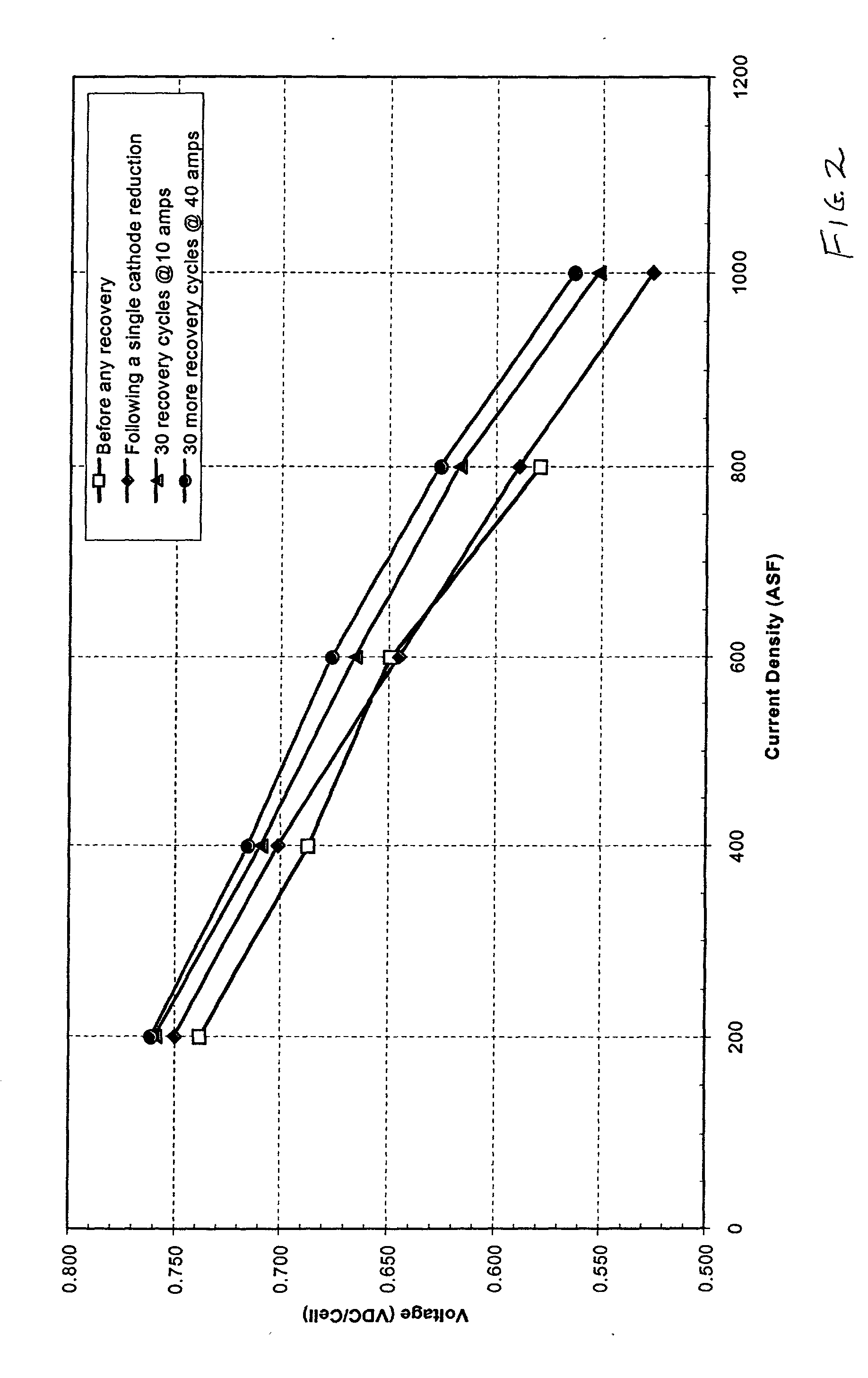
[0001] This invention relates to recovering performance in a fuel cell in which the voltage current characteristic has deteriorated over a long period of time of normal use (such as 500 hours or more), by performing at least 20 recurring cycles of on the order of ten seconds of oxidant gas starvation at the cathode.[0002] It is known that operation of PEM (polymer electrolyte membrane) fuel cells for extended periods (several hundred or more hours) results in performance decay; that is, a reduction in output voltage at any given current density. It is also known that operating the fuel cell without oxidant tends to rejuvenate the fuel cell so that its performance is at least substantially recovered as is described, for instance, in U.S. Pat. No. 4,294,892. In PCT International Publication No. WO 01 / 01508, rejuvenation is carried out while the fuel cell continues to generate power by causing oxidant starvation of only a portion of each cell at any moment, or by periodic momentary oxi...

Claims


Application Information

Patent Timeline
Patent Type & Authority Applications(United States)
IPC IPC(8): H01M8/00H01M8/04H01M8/10
CPCH01M8/04029Y02E60/50H01M2008/1095H01M8/04223H01M8/241H01M8/0267H01M8/2457H01M8/04228
Inventor REISER, CARL A.BALLIET, RYAN J.
Owner AUDI AG
Learn More