Industrial hollow cathode

a hollow cathode and hollow cathode technology, applied in the field of hollow cathodes, can solve the problems of delcroix tubular cathodes, decrepitation of bombarding ions, surface temperature decrease, etc., and achieve the effect of long operating life and simple fabrication and us

Inactive Publication Date: 2004-01-01
KAUFMAN & ROBINSON
View PDF9 Cites 19 Cited by
  • Summary
  • Abstract
  • Description
  • Claims
  • Application Information

AI Technical Summary

Benefits of technology

0011] In light of the foregoing, it is a general object of the invention to provide a...

Problems solved by technology

Conversely, if the emission is high, the discharge voltage decreases, decreasing the energy of the bombarding ions and thereby decreasing the surface temperature.
The simple tubular cathode of Delcroix, et al., has a limited lifetime, typically a few tens of hours in the sizes and operating conditions of interest for ion sources.
While such a lifetime may be adequate for some applications, it is very short for the electron emission functions of many industrial ion sources.
However, exposure to atmosphere rapidly degraded the electron emission characteristics of the emission material--see Zuccaro in AIAA Paper 73-1140, 1973.
Reliability of resistive heater 27 has been an recurrent prob...

Method used


Image

  • Industrial hollow cathode
  • Industrial hollow cathode
  • Industrial hollow cathode

Examples


Embodiment Construction

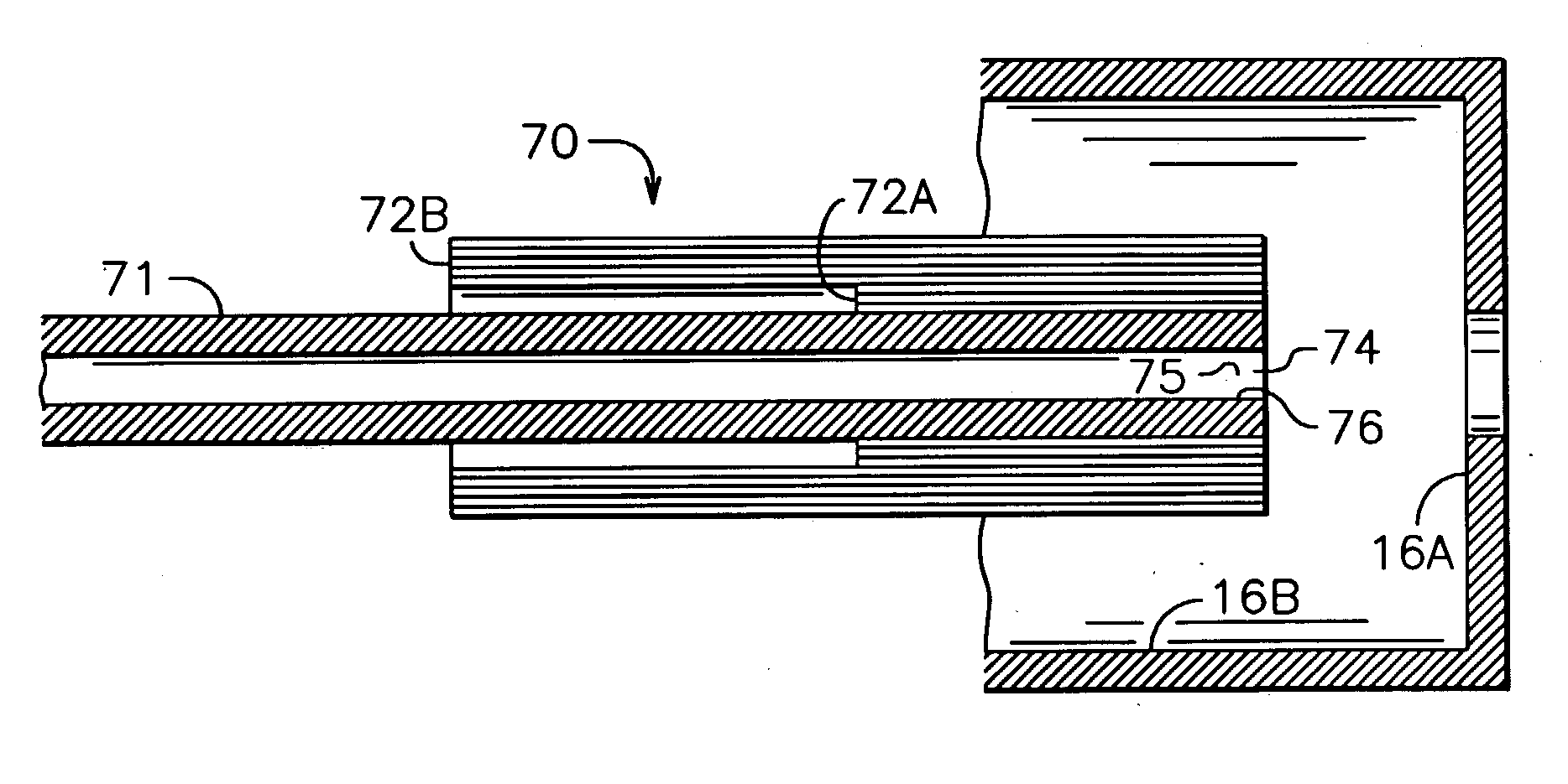
[0069] Referring to FIG. 8, there is shown the preferred embodiment of the present invention. Hollow cathode 70 comprises a hollow tantalum tube 71 and inner and outer radiation shields 72A and 72B. A shield is defined as a single layer that circumferentially encloses the hollow-cathode tube. Radiation shields 72A comprise a plurality of shields constructed of a spiral, multiple-turn winding of tantalum foil, wound external to the hollow cathode tube 71. Radiation shields 72B comprise a second plurality of shields, also constructed of a spiral, multiple-turn winding of tantalum foil, external to both hollow-cathode tube 71 and radiation shields 72A. The ends of shields 72A and 72B are both approximately even with the open end of tube 71. The electrons that pass through aperture 74 come from volume 75 near the aperture, and mostly originate from internal tube surface 76 adjacent to volume 75. An enclosed keeper with apertured end 16A and cylindrical wall 16B is also shown in FIG. 8.

[...


PUM


Abstract

In accordance with one embodiment of the present invention, the hollow-cathode apparatus comprises a small-diameter tantalum tube with a plurality of tantalum-foil radiation shields, wherein the plurality of shields in turn comprise one or more spiral windings external to that tube and approximately flush with the open end from which electron emission takes place. The axial length of at least one of the inner windings (closer to the tantalum tube) is equal to or less than approximately half the length of the tantalum tube. An enclosed keeper surrounds the cathode. To start the cathode, a flow of ionizable inert gas, usually argon, is initiated through the cathode and out the open end. An electrical discharge is then started between the keeper and the hollow cathode. When heated to operating temperature, electrons exit from the open end of the hollow cathode.

Description

[0001] This application is based upon, and claims priority from, our Provisional Application No. 60 / 392,187, filed Jun. 27, 2002.[0002] This invention relates generally to hollow cathodes, and more particularly it pertains to hollow cathodes used to emit electrons in industrial applications.[0003] Hollow cathodes are used to emit electrons in a variety of industrial applications. As described in a chapter by Delcroix, et al., in Vol. 35 of Advances in Electronics and Electron Physics (L. Marton, ed.), Academic Press, New York (1974), beginning on page 87, there are both high and low pressure regimes for hollow-cathode operation. In the high-pressure regime, the background pressure (the pressure in the region surrounding the hollow cathode) approaches or exceeds 1 Torr (130 Pascals) and no internal flow of ionizable working gas is required for operation. In the low-pressure regime with a background pressure below 0.1 Torr, an internal flow of ionizable working gas is required for eff...

Claims


Application Information

Patent Timeline
IPC IPC(8): H01J1/02H01J1/52
CPCH01J1/52H01J1/025
Inventor KAUFMAN, HAROLD R.KAHN, JAMES R.
Owner KAUFMAN & ROBINSON
Why Eureka
Try Eureka