Initiating operation of an electric vehicle or other load powered by a fuel cell at sub-freezing temperature

a technology of fuel cell and electric vehicle, which is applied in the direction of electrochemical generator, cell component details, cell components, etc., can solve the problems of less satisfactory performance of other experiments, potential mechanical damage, and the ability of the vehicle to operate, so as to improve the initiation of the fuel cell

Inactive Publication Date: 2004-01-01
AUDI AG
View PDF0 Cites 34 Cited by
  • Summary
  • Abstract
  • Description
  • Claims
  • Application Information

AI Technical Summary

Benefits of technology

0005] Objects of the invention include: operating, at subfreezing temperature, an electric vehicle powered by a fuel cell within seconds of initiation; improved initiation of fuel cell powered, electric vehicle operation at subfreezing temperature; initiating fuel cell powered electric vehicle operation at subfreezing temperature with a minimal of waste power used for raising the temperature of apparatus and / or fluids; avoiding the need for heat exchangers and other apparatus to heat reactants or coolants above freezing; and avoiding use of battery power to start a fuel cell for powering a vehicle.

Problems solved by technology

It is generally agreed that one difficulty with utilizing fuel cells to power the propulsion system of electric vehicles is the requirement that such vehicles be operable at temperatures below that at which water will freeze.
Freezing provides potential mechanical damage as a consequence of the expansion of ice, and presents problems due to the inseparability of water and the fuel cell processes.
Performance of other experiments were less satisfactory.
None of the foregoing are capable of providing fuel cells operable in subfreezing temperatures, particularly as low as -40.degree. C.

Method used


Image

  • Initiating operation of an electric vehicle or other load powered by a fuel cell at sub-freezing temperature
  • Initiating operation of an electric vehicle or other load powered by a fuel cell at sub-freezing temperature
  • Initiating operation of an electric vehicle or other load powered by a fuel cell at sub-freezing temperature

Examples


Embodiment Construction

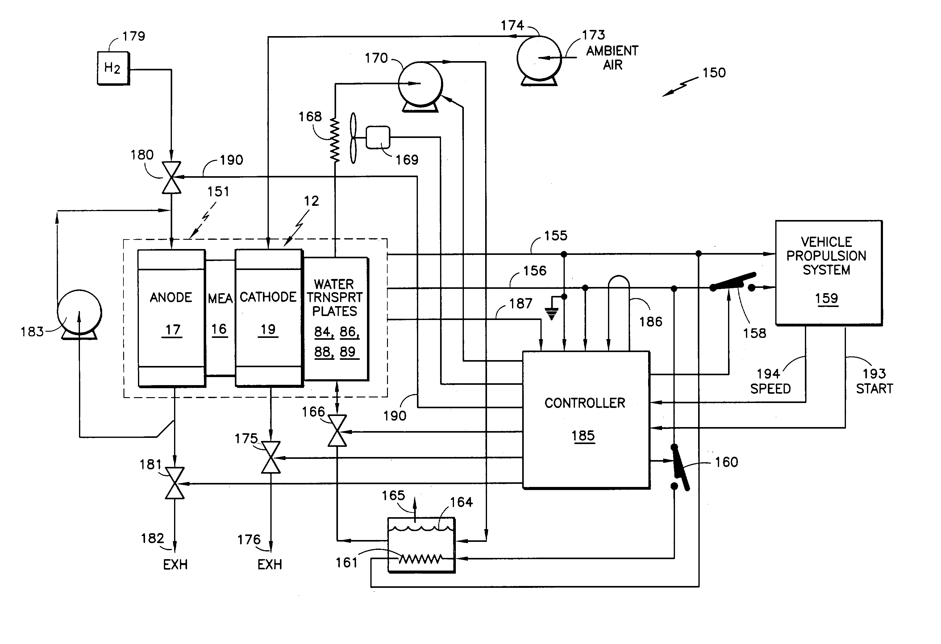
[0021] The invention may be used with a wide variety of fuel cell stacks, having fuel cells of various configurations.

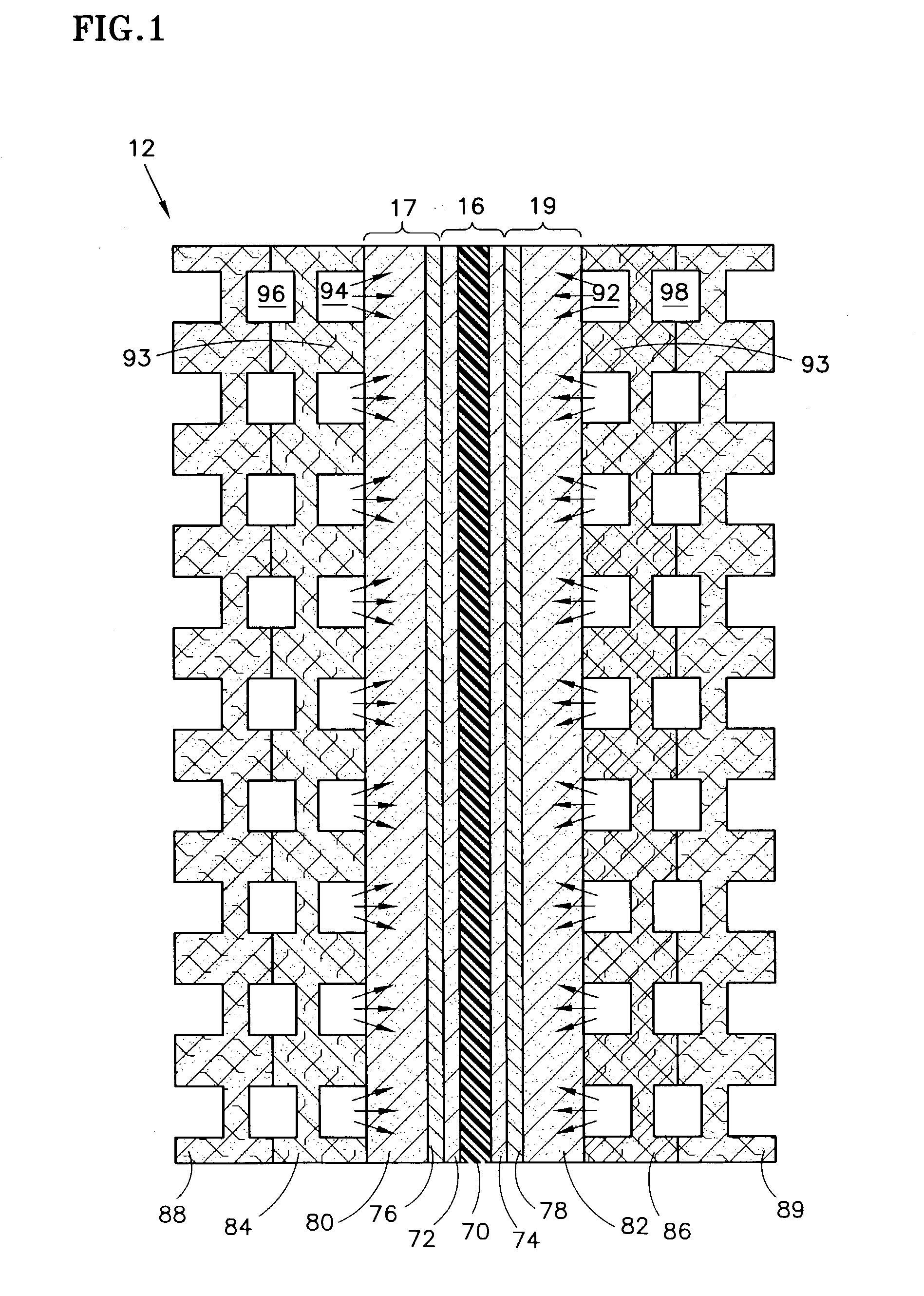
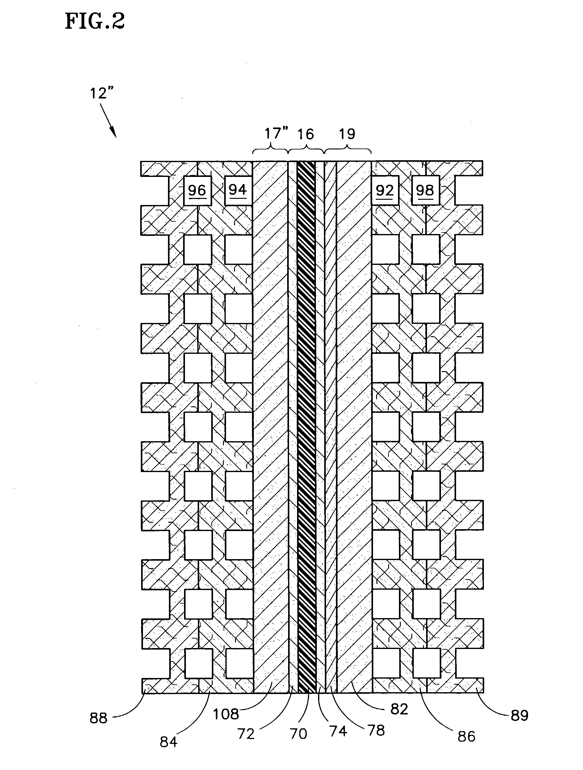
[0022] Referring to FIG. 1, there is shown a cross sectional view of a typical fuel cell 12, which includes a membrane electrode assembly (MEA) 16, an anode support plate 17 and a cathode support plate 19. The MEA 16 comprises a polymer electrolyte membrane ("PEM") 70, an anode catalyst 72 and a cathode catalyst 74. The anode catalyst 72 and the cathode catalyst 74 are secured on opposite sides of the PEM 70.

[0023] The anode support plate 17 and cathode support plate 19 may include hydrophobic diffusion layers 76, 78 and hydrophilic substrate layers 80, 82. The anode diffusion layer 76 is adjacent to a side of the anode catalyst 72, and the anode substrate layer 80 is adjacent to the anode diffusion layer 76 opposite the anode catalyst 72. The anode diffusion layer 76 and the hydrophilic anode substrate layer 80 allow the fuel reactant gas, which passes through a pas...


PUM

PropertyMeasurementUnit
atmospheric pressureaaaaaaaaaa
pressureaaaaaaaaaa
temperatureaaaaaaaaaa

Abstract

A vehicle (150) includes a fuel cell stack (151) started when the stack is below freezing, by connection (158) to the vehicle propulsion system (159) within a few seconds of starting the flow of fuel (179) and oxidant (173), or when open circuit voltage (155, 156) is detected. The fuel is in excess of stochiometry requirement and the oxidant is in excess of at least twice stochiometric requirement, either may be at about atmospheric pressure or at 4 kPa (0.6 psi) or more above the pressure of any water in said water passages, and either may be below freezing. Water transport plates (84, 86, 88, 89) have water passages connected to a water circulation loop (170) including a reservoir (164) having an auxiliary heater (161) connected (160) to the stack. Warming of cell stack materials and ice in the water transport plates, heat of fusion of melting ice, warming of melted water, and evaporative cooling of water melted in the water transport plates keep the fuel cell cool until liquid coolant can be circulated.

Description

[0001] This is a continuation-in-part of U.S. patent application Ser. No. 10 / 187,547 filed on Jul. 1, 2002.[0002] This invention relates to rapidly initiating operation of a fuel cell powered electric vehicle, at sub-freezing temperature, by means of one or more of: providing excess reactant gas or cold reactant gas to the proton exchange membrane (PEM) fuel cell stack which powers the load, such as a vehicle propulsion system, connecting the load to the stack within 20 seconds of reactant gas flow or when open circuit voltage is detected, previously draining hydrophilic support plates, connecting coolant only after several minutes or when sufficient water has melted.[0003] It is generally agreed that one difficulty with utilizing fuel cells to power the propulsion system of electric vehicles is the requirement that such vehicles be operable at temperatures below that at which water will freeze. Freezing provides potential mechanical damage as a consequence of the expansion of ice, ...

Claims


Application Information

Patent Timeline
Patent Type & Authority Applications(United States)
IPC IPC(8): H01M8/04
CPCH01M8/04022Y02E60/50H01M8/04223H01M8/04156H01M8/241H01M8/04302H01M8/04225H01M8/0267H01M8/2457H01M8/0258
Inventor REISER, CARL A.RESNICK, GENNADYPOPOVICH, NEIL A.
Owner AUDI AG
Why Eureka
Try Eureka