
Resin composition for use in manufacturing wet friction materials and wet friction material

Inactive Publication Date: 2004-01-08
ASAHI & MASUDA
View PDF1 Cites 49 Cited by
  • Summary
  • Abstract
  • Description
  • Claims
  • Application Information

AI Technical Summary

Benefits of technology

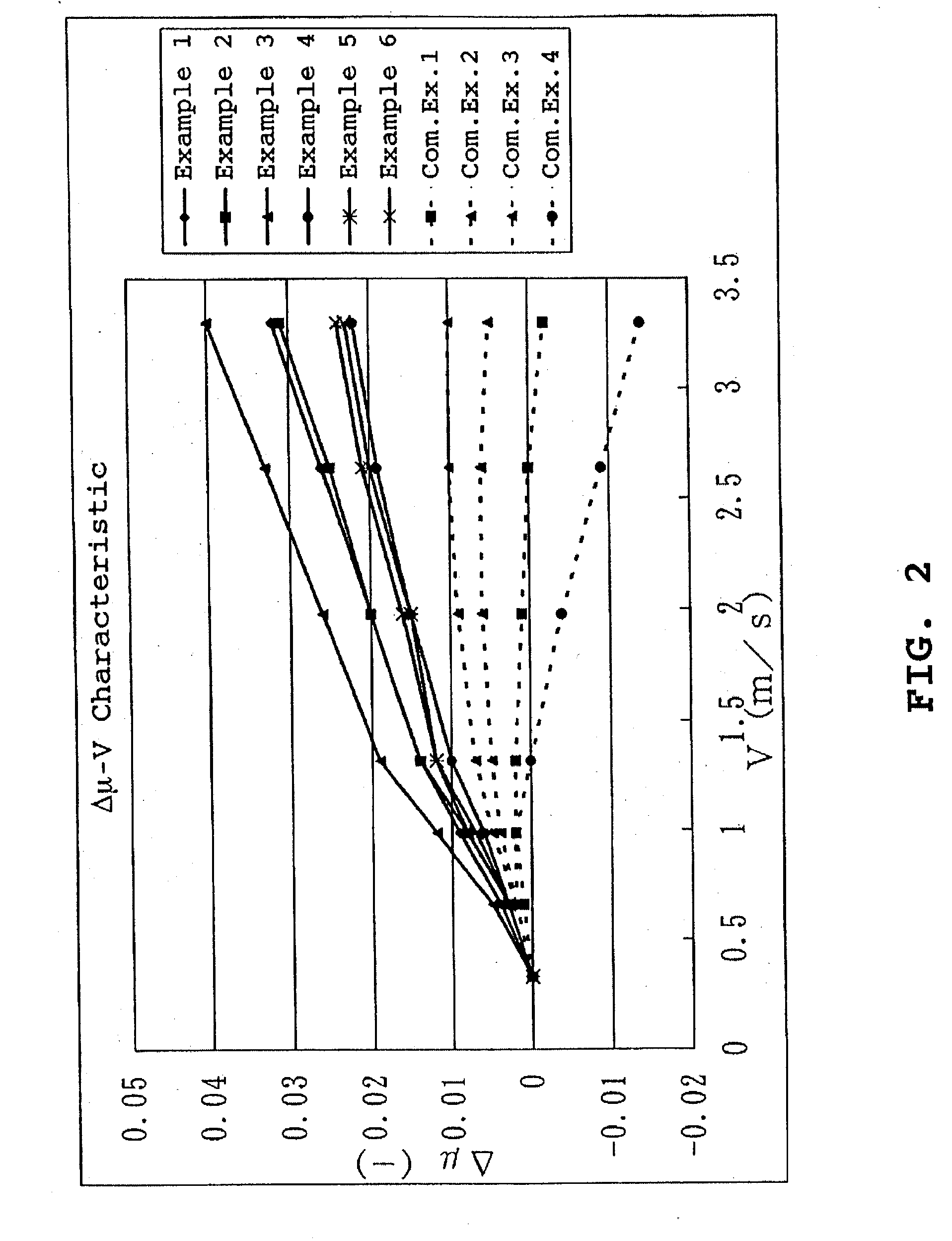
[0010] Also, it is another object of the present invention to provide a wet friction material which exhibits a small initial rate of change in friction coefficient, a large positive gradient of .DELTA..mu.-V characteristic, and high durability.

Problems solved by technology

Moreover, the thermosetting resin affects the frictional properties and the durability of a resultant wet friction material.
However, a wet friction material manufactured using such an unmodified phenolic resin as a binder involves the following problem.
Namely, since an unmodified phenolic resin has a high cross-linking density when cured, a wet friction material manufactured using such a resin becomes too rigid and therefore such a wet friction material causes uneven abutment with a separator plate when used.
That is, the initial rate of change in friction coefficient of such a wet friction material becomes necessarily large.
However, a problem exists with such modified phenolic resins in that wet friction materials manufactured using such modified phenolic resins are inferior to wet friction materials manufactured using an unmodified phenolic resin in heat resistance and compressive fatigue properties.
As of now, a modified phenolic resin capable of manufacturing wet friction materials having satisfactory durability has not yet been realized.
In addition, such a wet friction material manufactured using a modified phenolic resin is liable to exhibit .DELTA..mu.-V characteristic (friction coefficient-velocity) with negative gradient, thus resulting in the case that shift shock is caused when used in a clutch.
On the other hand, if the mole ratio in the reaction exceeds the above upper limit value, the cross-linking density of the resultant phenolic resin is increased so that the phenolic resin becomes excessively hard when cured, thus resulting in the case that the effect of decreasing the initial rate of change in friction coefficient of a wet friction material is lowered.
On the other hand, if the weight average molecular weight of the phenolic resin exceeds the above upper limit value, the viscosity of the resin is increased, thus resulting in the case that the impregnability of the phenolic resin into a fibrous base material is impaired.
If the water percentage of the phenolic resin is less than the above lower limit value, there is a case that the phenolic resin is difficult to be impregnated into a fibrous base material.
However, a problem exists with silica prepared using such a wet method in that it has high moisture absorbency due to its high concentration of silanol groups.
As a result, a wet friction material manufactured using a resin composition in which such silica is dispersed is liable to be swelled, which results in lowering in the strength and the durability of the manufactured wet friction material.
On the other hand, if the specific surface area of the particulate filler exceeds the above upper limit value, the particulate filler becomes excessively porous, thus resulting in the case that the strength of a wet friction material is lowered.
If the hydroxyl group density exceeds the above upper limit value, unsatisfactory dispersion of the particulate filler is liable to occur, thus resulting in the case that the durability of a wet friction material is lowered.
Further, since the moisture absorbency of a cured resin composition for wet friction materials has an effect on deterioration of a wet friction material, if the surface silanol group concentration of silicon dioxide is high, a resultant wet friction material exhibits high moisture absorbency, thus resulting in acceleration of deterioration of the wet friction material.
If the average particle size of a primary particle is less than the above lower limit value, there is a case that it is difficult to disperse the particulate filler because the particulate filler is very small in size so that agglomeration is liable to occur.
On the other hand, if the average particle size of a primary particle exceeds the above upper limit value, the size of the particulate filler is too large to satisfactorily disperse, thus resulting in the case that a resultant wet friction material can not exhibit stable friction coefficient.
On the other hand, if the amount of addition exceeds the above upper limit value, there is a case that a resultant wet friction material does not exhibit stable friction coefficient.
If the median diameter exceeds the above upper limit value, the particulate filler will not satisfactorily disperse, thus resulting in the case that a resultant wet friction material can not exhibit stable friction coefficient.

Method used


Image

  • Resin composition for use in manufacturing wet friction materials and wet friction material
  • Resin composition for use in manufacturing wet friction materials and wet friction material

Examples


example 1

[0065] Preparation of Phenolic Resin

[0066] 940 parts by weight of phenol, 895 parts by weight of 37% formalin (F / P=1.1), 20 parts by weight of ammonia water, and 10 parts by weight of 50% sodium hydroxide were put in a flask equipped with a stirrer, a reflux condenser, and a thermometer to be reacted at a temperature of 80.degree. C. for 1 hour. Thereafter, the resultant substance was subjected to dehydration in a vacuum of 110 mmHg, and then at the time when a temperature was reached to 75.degree. C., 370 parts by weight of methanol was added thereto. Then, the thus obtained substance was cooled, to thereby obtain a liquid phenolic resin containing a nonvolatile component of about 64.0 wt %, and having a weight average molecular weight of 358.

[0067] Preparation of Resin Composition for Wet Friction Materials

[0068] The liquid phenolic resin obtained in in the above was mixed with methanol and Fumed silica as a particulate filler (manufactured by TOKUYAMA Corp., with a product nam...

example 2

[0071] A wet friction material of Example 2 was manufactured in the same manner as Example 1 except that a different particulate filler was used, and a different dispersing apparatus was used.

[0072] In this Example, AEROSIL 130 (which is a name of a product manufactured by Nippon Aerosil Co., and has an average particle size of a primary particle of about 16 nm, a specific surface area of about 130 m.sup.2 / g, and a silanol group density of about 2 SiOH / nm.sup.2) was used as a particulate filler, and an ultrasonic generator was used as a dispersing apparatus. It is to be noted that the median diameter of the particulate filler in the obtained resin composition for wet friction materials was 10 .mu.m.

example 3

[0073] A wet friction material of Example 3 was manufactured in the same manner as Example 1 except that a different particulate filler was used, and a different dispersing apparatus was used.

[0074] In this Example, Fumed silica (manufactured by Nippon Aerosil Co., with a product name of AEROSIL 200, and having an average particle size of a primary particle of about 12 nm, a specific surface area of about 200 m.sup.2 / g, and a silanol group density of about 3 SiOH / nm.sup.2) was used as a particulate filler, and CLEARMIX (which is a trademark of a product manufactured by ORGANO CORPORATION) was used as a dispersing apparatus. It is to be noted that the median diameter of the particulate filler in the obtained resin composition for wet friction materials was 9 .mu.m.


PUM

PropertyMeasurementUnit
Lengthaaaaaaaaaa
Fractionaaaaaaaaaa
Particle sizeaaaaaaaaaa

Abstract

A resin composition for wet friction materials contains as a main component a phenolic resin formed as a result of the reaction between phenols and aldehydes in the presence of a basic catalyst, and a particulate filler having a specific surface area of 35 to 410 m<2> / g as an additive. A wet friction material is formed using the resin composition for wet friction materials described above as a binder. The thus formed wet friction material exhibits a small initial rate of change in friction coefficient, a large positive gradient of Deltamu-V characteristic, and excellent durability.

Description

[0001] 1. Field of the Invention[0002] This invention relates to a resin composition for use in manufacturing wet friction materials, and a wet friction material manufactured using the resin composition.[0003] 2. Description of the Prior Art[0004] In automatic transmissions of vehicles and the like, wet friction materials are used. Generally, such an automatic transmission is provided with a multi-plate clutch in which a plurality of friction plates having wet friction materials are arranged in an alternate relation with separator plates which serve as friction mating members. Each of the friction plates is formed by adhering wet friction materials to both surfaces of a metallic core plate. Each of the separator plates is formed from a single plate such as a metallic plate. The multi-plate clutch is operative in ATF (automatic transmission fluid) which is used as a lubricant to transmit power or cut off power transmission by engaging these friction plates and separator plates or rel...

Claims


Application Information

Patent Timeline
IPC IPC(8): C08G8/10C08K3/14C08K3/22C08K3/28C08K5/00C08L61/06C09K3/14D21H17/48D21H17/68D21H21/52F16D69/02
CPCC08G8/10C08K3/14F16D2200/0095F16D69/026D21H21/52D21H17/74D21H17/68C08K3/22C08K3/28D21H17/48C08L61/06
Inventor AIBA, HIROSHIMORI, MASAHIRO
Owner ASAHI & MASUDA
Learn More