Fabrication of functional device mounting board making use of inkjet technique

a functional device and inkjet technology, applied in the direction of inking apparatus, conductive pattern formation, instruments, etc., can solve the problems of insufficient reference, difficult application of inkjet technique to fabricate functional devices, and inability to meet the needs of users, so as to prevent undesirable clogging and ensure reliable ejection operation

Inactive Publication Date: 2004-01-15
RICOH KK
View PDF21 Cites 71 Cited by
  • Summary
  • Abstract
  • Description
  • Claims
  • Application Information

AI Technical Summary

Benefits of technology

[0011] It is still another object of the invention to prevent undesirable clog in the jet head in order to guarantee reliable ejecting operation.

Problems solved by technology

However, since vacuum evaporation and photolithography are high-cost processes requiring a number of steps, it is disadvantageous to employ these techniques to fabricate luminescent devices over a wide area.
However, these publications only discuss the materials for organic EL devices suitable to the inkjet method, and do not sufficiently refer to either an apparatus for forming such a functional device on a substrate using an inkjet technique, or a functional device mounting board fabricated using the inkjet technique.
Applying the inkjet technique to fabrication of functional devices is not easy because the conventional inkjet technique is limited to ejecting ink onto paper.
There are still many unsolved factors concerning how to eject a solution containing a functional material onto a substrate in a stable manner.
Especially, a great deal of work is required to realize a group of functional devices formed on a substrate at highly precise patterns efficiently.

Method used


Image

  • Fabrication of functional device mounting board making use of inkjet technique
  • Fabrication of functional device mounting board making use of inkjet technique
  • Fabrication of functional device mounting board making use of inkjet technique

Examples


Embodiment Construction

[0098] The details of the present invention will now be described with reference to the attached drawings.

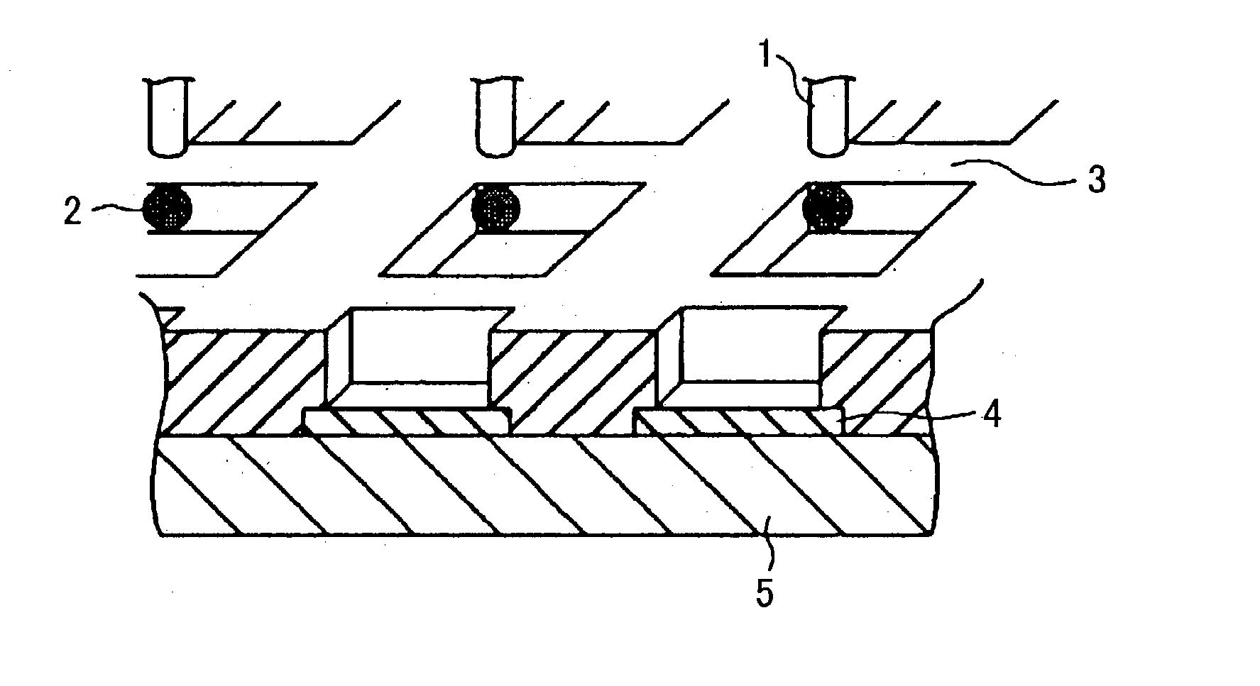
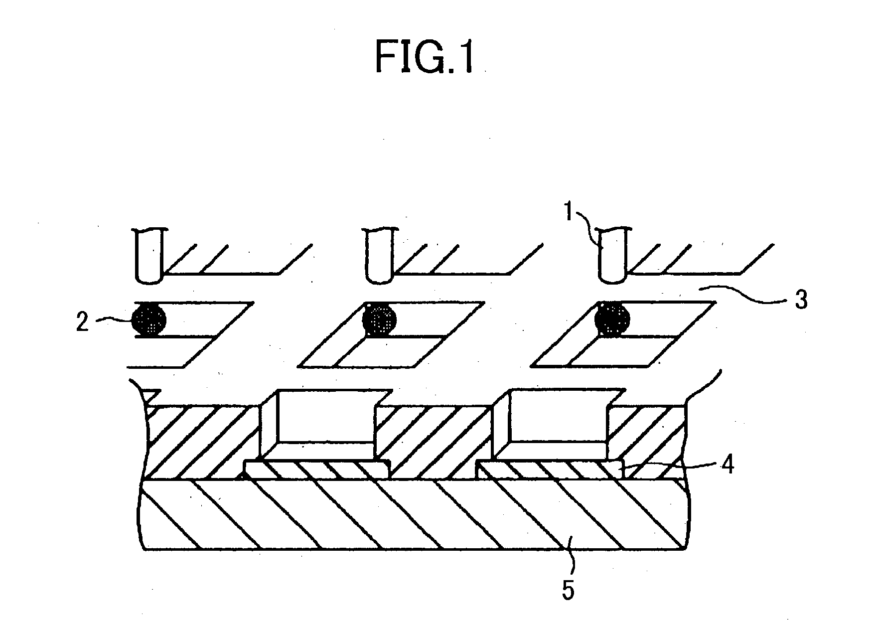
[0099] FIG. 1 illustrates fabrication of organic EL devices as an example of the functional devices. In this example, solution 2, in which organic EL material that emits light of red, green, or blue is dissolved, is ejected from a nozzle 1 onto an ITO (indium tin oxide) transparent electrode patterns 4 formed on glass substrate 5. The glass substrate 5 has a barrier wall 3 that defines an array of the transparent electrode pattern 4, and the organic EL devices of the corresponding colors of red, green, and blue are arranged as a mosaic pattern. The composition of the solution 2 is as given below:

[0100] Solvent: dodecylbenzene / dichlorobenzene (1 / 1, volume ratio)

[0101] Red: polyfluorene / perylene dye (98 / 2, weight ratio)

[0102] Green: polyfluorene / coumarin dye (98.5 / 1.5, weight ratio)

[0103] Blue: polyfluorene

[0104] The ratio of the solid material to solvent is given as 0.4% (weight / ...


PUM


Abstract

An apparatus for fabricating a functional device mounting board comprises a holder for holding a substrate on which functional devices are to be formed, a jet head for ejecting a droplet containing a functional material onto the substrate, and a data input unit for supplying droplet ejection information to the jet head. The jet head ejects the droplets onto the substrate based on the droplet ejection information so as to form the functional device in the functional device forming area. The functional device is formed by allowing a volatile ingredient of the droplet, while allowing a solid component of the droplet to remain on the substrate.

Description

[0001] 1. Field of the Invention[0002] The present invention generally relates to fabrication of a functional device mounting board, using an ejector to form a functional device on a substrate. More particularly, the present invention relates to an apparatus and a system for fabricating the functional device mounting board, as well as a functional device mounting board itself fabricated using the apparatus or the system.[0003] 2. Description of the Related Art[0004] In recent years, luminescent devices (or light-emitting devices) using organic materials have been developed for use in a spontaneous luminescent display, which has been spreading in place of a liquid crystal display. In general, the luminescent device is formed using a photolithography technique to pattern a layer of a functional material into a predetermined shape. For example, it is-known that an organic electroluminescent (hereinafter, referred to as "organic EL") device is fabricated by forming a layer of a low mole...

Claims


Application Information

Patent Timeline
Patent Type & Authority Applications(United States)
IPC IPC(8): B05B13/04B41J2/01B41J2/14B41J2/175G02B5/20H01L51/50H05B33/02H05B33/10H05B33/12H05K3/12
CPCB41J2/14016B41J2202/09H05K3/1241G02B5/201H01L51/5237B41J2202/20H10K50/841
Inventor SEKIYA, TAKURO
Owner RICOH KK
Why Eureka
Try Eureka