
State-of-charge detector device, program thereof, state-of-charge detecting method, and charge-discharge control device

a detector device and state-of-charge technology, applied in the direction of instruments, electrochemical generators, transportation and packaging, etc., can solve the problems of device difficulty in detecting device cannot precisely determine whether the battery has reached the fully charged state, and the temperature of a secondary battery is considerably affected

Inactive Publication Date: 2004-01-22
NIPPON SOKEN +1
View PDF1 Cites 24 Cited by
  • Summary
  • Abstract
  • Description
  • Claims
  • Application Information

AI Technical Summary

Benefits of technology

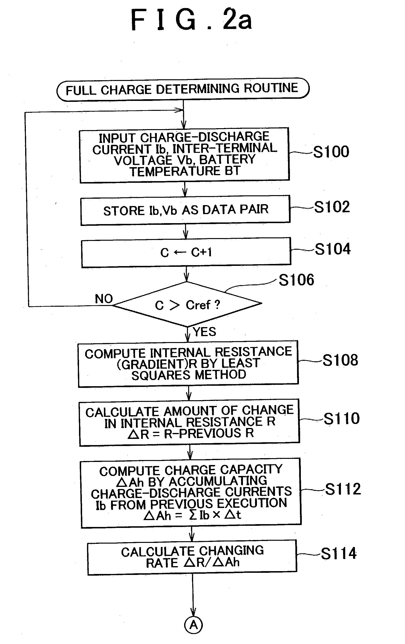
[0009] The above-described state-of-charge detector device calculates the internal resistance of the secondary battery based on the current through the secondary battery detected by the current detector and the voltage between the terminals of the secondary battery detected by the voltage detector, and calculates the rate of change in the internal resistance with respect to the amount of charge stored in the secondary battery, and determines the state of charge of the secondary battery based on the calculated rate of change in the internal resistance. The internal resistance of a secondary battery rises as the secondary battery is charged. Immediately before the fully charged state is reached, the internal resistance of the secondary battery inflects and then decreases. That is, the rate of change in the internal resistance with respect to the amount of charge stored in the secondary battery shifts from the positive side to the negative side at a predetermined reference point immediately prior to the fully charged state. Therefore, the state of charge can be determined on the basis of the rate of change in the internal resistance. In particular, the precision in detection of the state of charge immediately prior to the full charge can be improved.
[0012] The above-described program causes a computer connected to the current detector and the voltage detector to function as a state-of-charge detector device according to the invention. Therefore, the program achieves advantages similar to those of the state-of-charge detector device of the invention. For example, the program is able to determine the state of charge of a secondary battery based on the rate of change in the internal resistance and, more particularly, is able to improve the precision in detection of the state of charge immediately preceding the fully charged state.
[0015] In the above-described state-of-charge detecting method of the invention, the internal resistance of the secondary battery is calculated on the basis of the electric current through the secondary battery detected by the current detector, and the voltage between the terminals of the secondary battery detected by the voltage detector. Furthermore, the rate of change in the internal resistance with respect to the amount of charge stored in the secondary battery is calculated. On the basis of the calculated rate of change in the internal resistance, the state of charge of the secondary battery is determined. The internal resistance of a secondary battery rises as the secondary battery is charged. Immediately prior to the fully charged state of the secondary battery, the internal resistance inflects and then decreases. That is, the rate of change in the internal resistance with respect to the amount of charge stored in the secondary battery shifts from the positive side to the negative side at a predetermined point immediately prior to the fully charged state. Therefore, the state of charge can be determined on the basis of the rate of change in the internal resistance. In particular, the precision in detection of the state of charge immediately prior to the full charge can be improved.
[0018] This charge-discharge control device controls the charging and discharging of the secondary battery on the basis of the state of charge detected by the above-described state-of-charge control device. If the electric current input to the secondary battery is curbed so as to restrict the charging of the secondary battery as the secondary battery approaches the fully charged state, for example, when the rate of change in the internal resistance with respect to the amount of charge undergoes a positive-to-negative shift, it becomes possible to more reliably accomplish the charging of the secondary battery without allowing the over-charging thereof.

Problems solved by technology

However, in some cases, the former device, which detects the fully charged state on the basis of the inter-terminal voltage, has a drawback as follows.
In such a case, the discrimination of the inter-terminal voltage with reference to the predetermined threshold value is likely to have an error, and therefore the device cannot precisely determine whether the battery has reached the fully charged state.
The latter device, which detects the fully charged state when the inter-terminal voltage of a secondary battery has decreased by a predetermined amount after reaching a peak, has a drawback as follows.
In such cases, the device will face difficulty in detecting the fully charged state.
However, the temperature of a secondary battery is considerably affected by various factors, such as the configuration of the battery, the heat capacity thereof, the charging speed, the heat generation based on internal resistance, etc.
Therefore, it is very difficult for these devices to detect the fully charged state of a secondary battery with high precision under precise condition setting.

Method used


Image

  • State-of-charge detector device, program thereof, state-of-charge detecting method, and charge-discharge control device
  • State-of-charge detector device, program thereof, state-of-charge detecting method, and charge-discharge control device
  • State-of-charge detector device, program thereof, state-of-charge detecting method, and charge-discharge control device

Examples


Embodiment Construction

[0026] In the following description and the accompanying drawings, the present invention will be described in more detail with reference to exemplary embodiments.

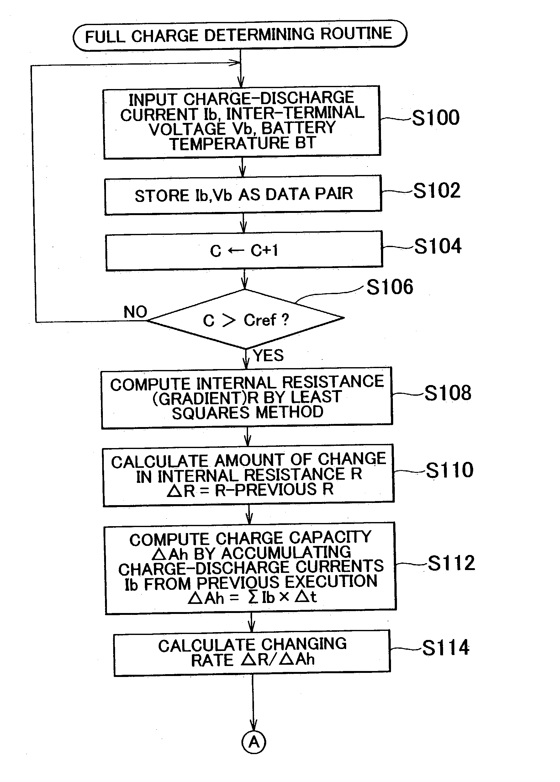
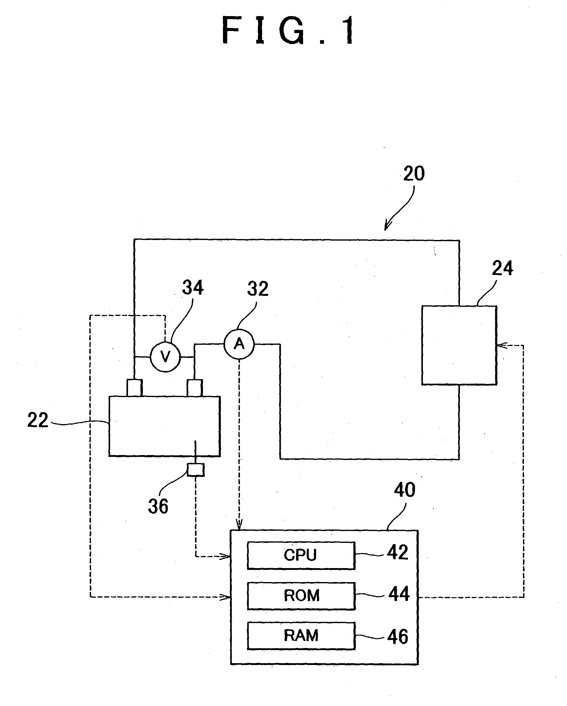
[0027] An exemplary embodiment of the invention will be described below. FIG. 1 is a schematic diagram illustrating a construction of a charge-discharge control device 20 that also functions as a state-of-charge detector device. As shown in FIG. 1, the charge-discharge control device 20 is designed so as to control the charging and discharging of a secondary battery 22 (e.g., a nickel metal hydride battery) that is connected to a load 24. The control device 20 has a current sensor 32 for detecting the electric current through the secondary battery 22, a voltage sensor 34 for detecting the voltage between terminals of the secondary battery 22, a temperature sensor 34 for detecting the temperature of the secondary battery 22, and an electronic control unit 40 for controlling the entire device. For example, if the charge-disch...


PUM

PropertyMeasurementUnit
electric currentaaaaaaaaaa
voltageaaaaaaaaaa
internal resistanceaaaaaaaaaa

Abstract

A state-of-charge detector device for detecting the state of charge of a secondary battery is provided. The device has a current detector that detects an electric current through the secondary battery, a voltage detector that detects a voltage between terminals of the secondary battery, and an internal resistance calculator that calculates an internal resistance of the secondary battery based on the detected current and the detected voltage. Furthermore, an internal resistance changing rate calculator is provided which calculates a rate of change in the internal resistance calculated, with respect to an amount of charge stored in the secondary battery. A state-of-charge deterrninator determines a state of charge of the secondary battery based on the rate of change in the internal resistance calculated.

Description

INCORPORATION BY REFERENCE[0001] The disclosure of Japanese Patent Applications No. 2002-212828 filed on Jul. 22, 2002, including the specification, drawings and abstract is incorporated herein by reference in its entirety.[0002] 1. Field of the Invention[0003] The invention relates to a state-of-charge detector device, a program thereof, and a full charge determining method. More particularly, the invention relates to a state-of-charge detector device for detecting the state of charge of a secondary battery, and a program that causes a computer to function as a secondary battery charge-discharge determining device, as well as a state-of-charge detecting method for detecting the state of charge of a secondary battery, and a charge-discharge control device for controlling the charging and discharging of a secondary battery.[0004] 2. Description of the Related Art[0005] Conventionally proposed devices of the aforementioned type for detecting the state of charge of a secondary battery ...

Claims


Application Information

Patent Timeline
Patent Type & Authority Applications(United States)
IPC IPC(8): G01R31/36H01M10/48H02J7/00H02J7/10
CPCG01R31/3648H02J7/0047G01R31/3662G01R31/389H02J7/0049
Inventor SAKAKIBARA, TERUHIKOSAKAI, SHOJINAKAYAMA, YOSHIYUKI
Owner NIPPON SOKEN
Learn More