Dielectric particles in optical waveguides for improved performance

Inactive Publication Date: 2004-01-22
CABOT MICROELECTRONICS CORP
View PDF16 Cites 17 Cited by
  • Summary
  • Abstract
  • Description
  • Claims
  • Application Information

AI Technical Summary

Problems solved by technology

This type of uniform core is highly susceptible to modal dispersion (MD) with higher order modes propagating more slowl

Method used


Image

  • Dielectric particles in optical waveguides for improved performance
  • Dielectric particles in optical waveguides for improved performance

Examples


Embodiment Construction

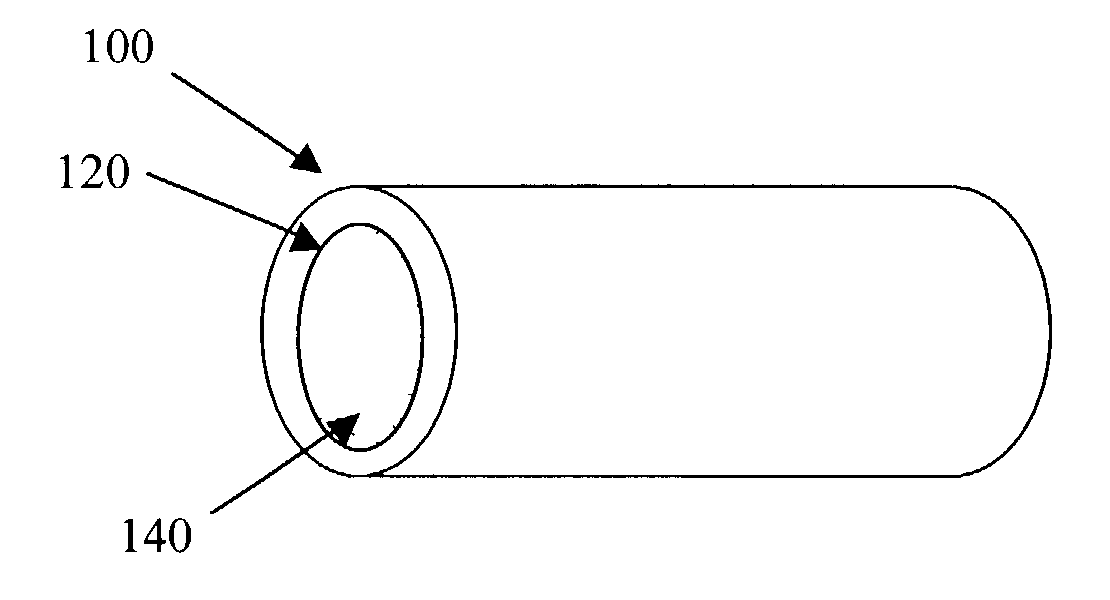
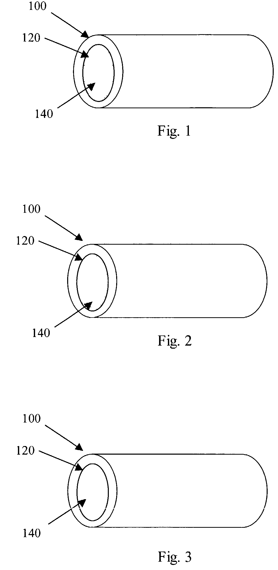
[0016] Dispersion plays an important role in the ultimate performance of optical waveguides. There are two predominant types of dispersion: chromatic dispersion, and modal dispersion. Chromatic dispersion is the variation in the velocity of light traveling within a waveguide with changes in optical frequency. An optical data pulse traveling through a waveguide always contains a spectrum of frequencies which typically travel at different speeds. Thus, some frequency components arrive at the output earlier than others. The difference in arrival times of the various frequencies in the pulse results in distortion of the signal in the time domain and therefore broadening of the pulse. The broadened pulse is susceptible to errors when converted into a digital signal.

[0017] Modal dispersion (MD) is the measure of the difference in arrival times of parts of a single optical signal which is distributed among the various confined modes of an MMF. In the case of SI-MMF, higher order modes trav...


PUM


Abstract

A multimode optical waveguide having reduced modal dispersion. The optical waveguide comprises a core, a cladding surrounding the core, and a plurality of optical scattering elements dispersed in the core.

Description

[0001] 1. Field of the Invention[0002] This invention relates to multi-mode optical waveguides having reduced modal dispersion.[0003] 2. Description of the Related Art[0004] Optical waveguides, such as optical fibers, consist of two basic components; a core and a cladding layer. A protective layer can cover the cladding and the core. The protective layer adds mechanical strength to the fiber to prevent cracking and breaking. Generally, the core has a higher index of refraction than the cladding thereby confining light in the core with minimal loss of intensity into the cladding. This phenomenon is sometimes referred to as total internal reflection.[0005] There are two well-known types of optical fibers, with distinctive properties. These are single mode fibers (SMF) and multi-mode fibers (MMF). Single-mode fibers have small core diameters, typically 2 to 10 wavelengths, and confine the propagating light to a single optical mode. Multi-mode optical fibers have a relatively large core...

Claims


Application Information

Patent Timeline
IPC IPC(8): G02B6/02G02B6/14
CPCG02B6/14G02B6/0229
Inventor MIKOLAS, DAVID G.
Owner CABOT MICROELECTRONICS CORP
Why Eureka
Try Eureka