Transparent electromagnetic wave-shielding laminate for display, process for producing same and display unit

a technology of electromagnetic shielding and laminate, applied in the direction of optics, thin material processing, instruments, etc., can solve the problems of electroconductive tape needing a lot of labor, failure to exert electromagnetic shielding performance, and electromagnetic interference to other machinery and equipmen

Inactive Publication Date: 2004-01-29
NISSHINBO IND INC
View PDF0 Cites 47 Cited by
  • Summary
  • Abstract
  • Description
  • Claims
  • Application Information

AI Technical Summary

Problems solved by technology

In addition, obstructions due to the electromagnetic wave to other machinery and equipment become problematic.
In the meanwhile, it is a problem of practical importance how is the electromagnetic wave-shielding layer is grounded, said layer being in the above-mentioned electromagnetic wave-shielding laminate (front sheet for display) for display.
Unless it is properly grounded, there is brought about such a disadvantage that the electromagnetic wave can not escape as electric current, thereby failing to exert the electromagnetic wave-shielding performance.
However, the method comprising sticking the electroconductive tape needs much labor in sticking the tape to the periphery of the electromagnetic wave-shielding laminate and in particular, cutting and sticking of the tape at corner portions are troublesome.
The electroconductive tape is apt to peel off, and since the terminal cross section portion of the electromagnetic wave-shielding layer is not always linearly formed, it is difficult to follow the unevenness on the peripheral portion of the electromagnetic wave-shielding laminate or a display side grounding portion while following the electromagnetic wave-shielding layer, whereby the grounding is prone to become incomplete.
This leads to a disadvan...

Method used


Image

  • Transparent electromagnetic wave-shielding laminate for display, process for producing same and display unit
  • Transparent electromagnetic wave-shielding laminate for display, process for producing same and display unit
  • Transparent electromagnetic wave-shielding laminate for display, process for producing same and display unit

Examples


preparation example 1

[0103] (Preparation of Electroconductive Elastomer Composition)

[0104] The materials at blending proportions as described hereunder were melt kneaded by the use of a twin-screw extruder to obtain pellets comprising a electroconductive elastomer composition. The resultant pellets were melt kneaded by the use of a twin-screw extruder to obtain electroconductive elastomer tape having 0.7 mm thickness and 20 mm width.

[0105] {Materials and Blending Proportions}

[0106] Ether Base Polyurethane Elastomer (Manufactured by Nisshinbo Industries Inc. under the trade name "Mobilon P24") . . . 100 parts by weight

[0107] Atomized powdery copper passing through 330 mesh (manufactured by Mitsui Mining and Smelting Co., Ltd. under the trade "MA-CD") . . . 400 parts by weight

[0108] Mn--Zn ferrite (manufactured by Toda Kogyo Corporation under the trade name "BSF-574") . . . 50 parts by weight

example 1

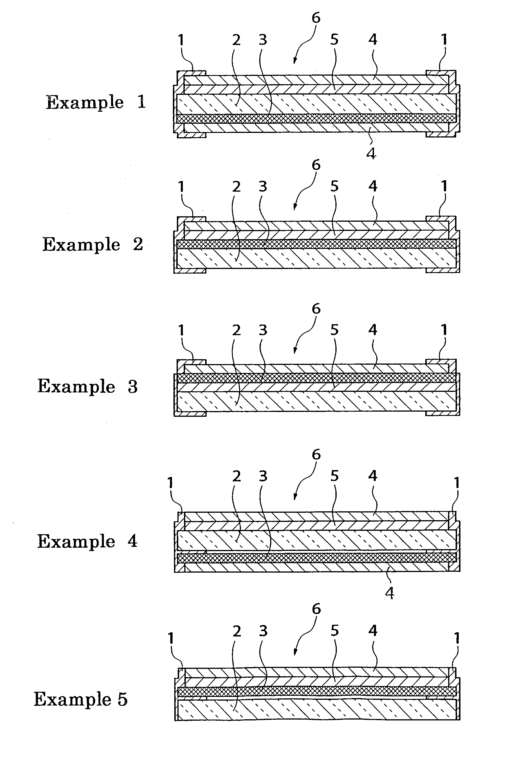
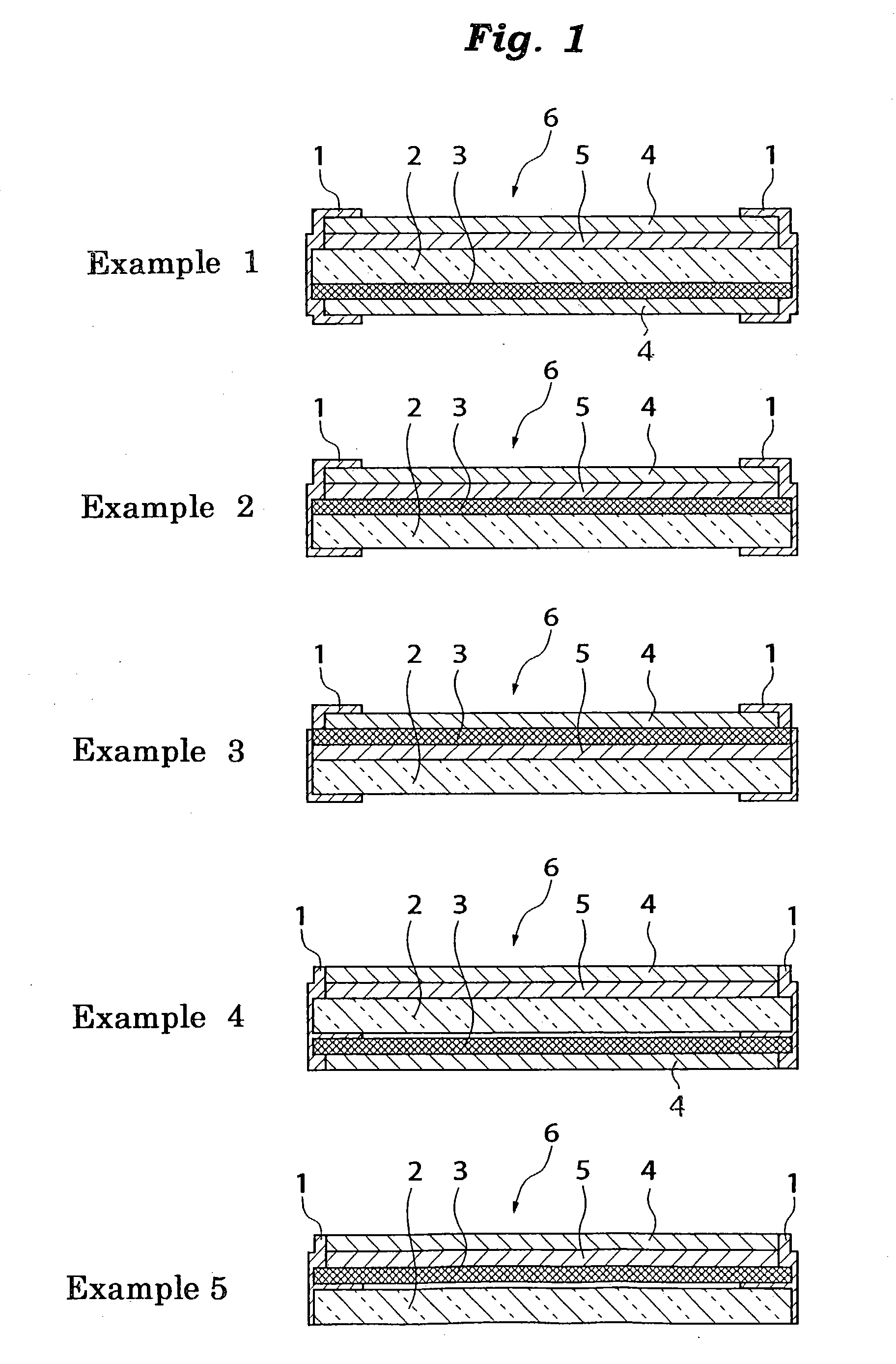
[0109] (A) Preparation of electromagnetic wave-shielding laminate having the exposed portion comprising the electroconductive elastomer composition (Example 1 in FIG. 1)

[0110] In accordance with the layer constitution as illustrated on Example 1 in FIG. 1, the members of each of the layers were laminated in the order of, viewed from the PDP module side, reflection prevention layer (4), electromagnetic wave-shielding layer (3), transparent substrate (2), near infrared ray-shielding layer (5) and reflection prevention layer (4) to obtain the electromagnetic wave-shielding laminate. During the lamination, the reflection prevention layer (4) to be located on the outside of the PDP module side for the electromagnetic wave-shielding layer, the reflection prevention layer (4) to be located on the outside of the audience side for the electromagnetic wave-shielding layer and the near infrared rayshielding layer (5) were each prepared and laminated in such dimensions that both length and widt...

example 2

[0120] (A) Preparation of electromagnetic wave-shielding laminate (Example 2 in FIG. 1)

[0121] In accordance with the layer constitution as illustrated on Example 2 in FIG. 1, the members of each of the layers were laminated in the order of, viewed from the PDP module (9) side, transparent substrate (2), electromagnetic wave-shielding layer (3), near infrared ray-shielding layer (5) and reflection prevention layer (4) to obtain the electromagnetic wave-shielding laminate. During the lamination, the reflection prevention layer (4) to be located on the outside of the audience side for the electromagnetic wave-shielding layer, and the near infrared ray-shielding layer (5) were each prepared and laminated in such dimensions that both length and width thereof were made to be 10 mm smaller than those of other members so that the edges of each side of the electromagnetic wave-shielding layer (3) were exposed by 10 mm.

[0122] The members used herein of each of the layers were the same as thos...


PUM

PropertyMeasurementUnit
Angleaaaaaaaaaa
Temperatureaaaaaaaaaa
Flow rateaaaaaaaaaa

Abstract

There are disclosed a transparent electromagnetic wave-shielding laminate for display, the laminate comprising an electromagnetic wave-shielding layer wherein at least periphery of a terminal cross section of the layer and/or periphery of an edge thereof is covered with an electroconductive elastomer composition containing an electroconductive filler and a thermoplastic elastomer; a process for producing an electromagnetic wave-shielding laminate comprising bringing an electroconductive elastomer composition into contact with at least periphery of a terminal cross section of an electromagnetic wave-shielding layer and/or periphery of an edge of the layer, and in this state, heat press bonding the composition from a lamination direction and/or cross sectional direction to form an exposed portion on at least peripheral end of the laminate, the portion comprising the composition which is grounded to the layer; other processes for producing the same; and a display unit comprising the transparent electromagnetic wave-shielding laminate. The above laminate, which is producible in high production efficiency, is capable of following the unevenness on the electromagnetic wave-shielding laminate and on the display side grounding portion, thereby surely enabling grounding connection and electromagnetic wave-shielding.

Description

[0001] 1. Field of the Invention[0002] The present invention relates to a transparent electromagnetic wave-shielding laminate which is excellent in grounding characteristics, a process for producing the laminate and a display unit. More particularly, it pertains to a transparent electromagnetic wave-shielding laminate for display which is capable of surely following the unevenness on the electromagnetic wave-shielding laminate or a display side grounding portion, and attaining not only sure grounding connection but also the prevention of electromagnetic wave leakage; a process for producing the laminate; and a display unit.[0003] 2. Description of the Related Arts[0004] It is said that a large amount of electromagnetic wave including non-ionizig radiation such as microwave and electric wave from the surfaces of displays of a variety of computers in office automation (OA) equipment and factory automation equipment and the surfaces of displays of game machines and television sets. In ...

Claims


Application Information

Patent Timeline
IPC IPC(8): G12B17/02G02F1/13H05K9/00
CPCG02F2001/133331Y10T428/12424H05K9/0096G02F2001/133334G02F1/133331G02F1/133334G12B17/02
Inventor BANNO, KOJIKUWABARA, SHINYOSHIDA, HIROSHI
Owner NISSHINBO IND INC
Why Eureka
Try Eureka