Method and devices for avoiding knocking on failure of an anti-knock regulator

a technology of anti-knock regulator and anti-knocking device, which is applied in the direction of mechanical equipment, machines/engines, electric control, etc., can solve the problems of engine efficiency loss

Inactive Publication Date: 2004-02-05
ROBERT BOSCH GMBH
View PDF5 Cites 76 Cited by
  • Summary
  • Abstract
  • Description
  • Claims
  • Application Information

AI Technical Summary

Problems solved by technology

However, one disadvantage of this is the loss...

Method used


Image

  • Method and devices for avoiding knocking on failure of an anti-knock regulator
  • Method and devices for avoiding knocking on failure of an anti-knock regulator
  • Method and devices for avoiding knocking on failure of an anti-knock regulator

Examples


Embodiment Construction

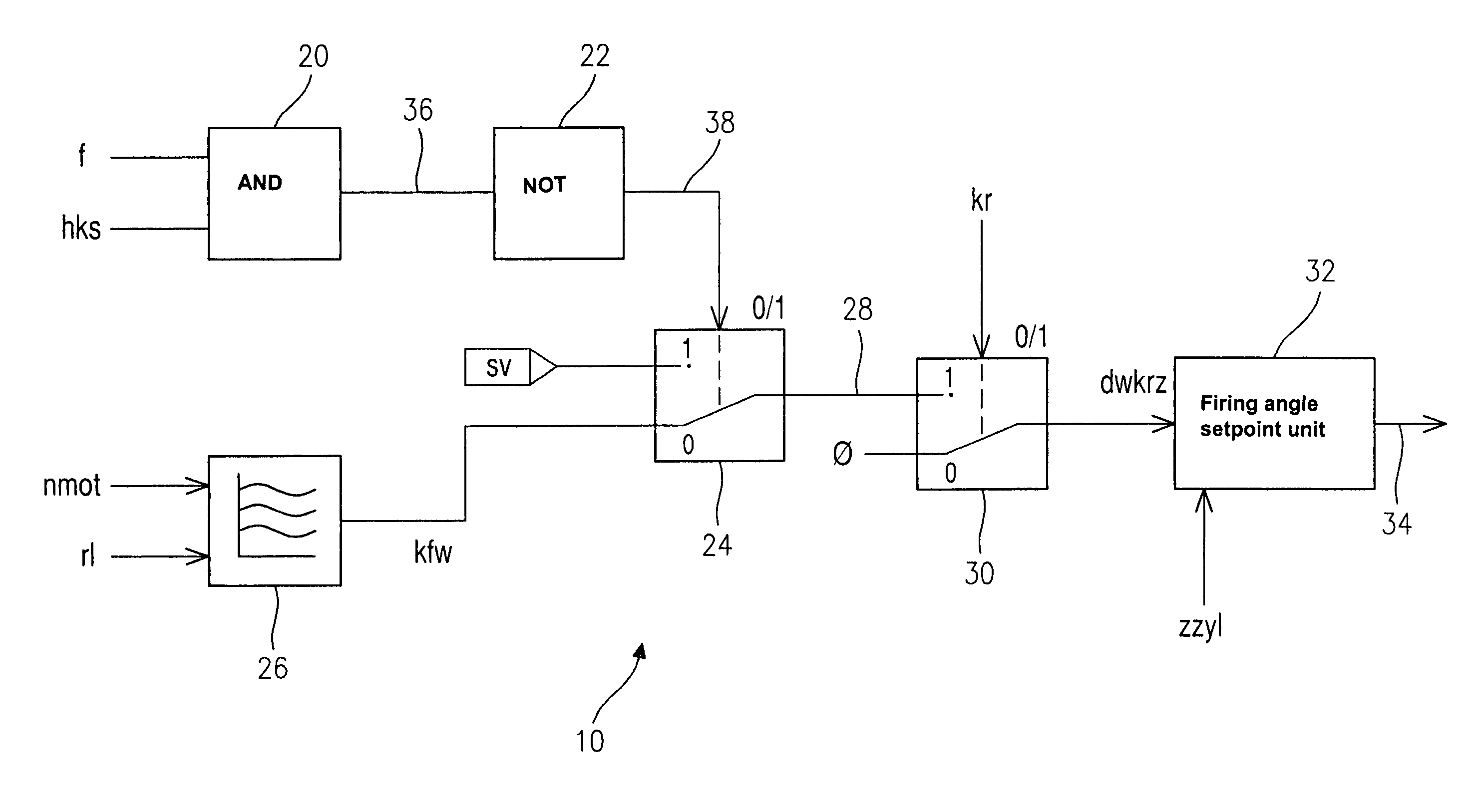
[0013] FIG. 1 shows a block diagram of part of a control circuit 10 for activating multiple injection in the event of failure of a knock control of a direct injection gasoline engine (not shown). Control circuit 10 contains an AND logic element 12 at whose one input an activation signal kr is applied and at whose other input a fault signal f is applied. Activation signal kr and fault signal f are generated by a controller of the firing system. Activation signal kr has the switch state logic ONE when the knock control is to be active. Fault signal f has the switch state logic ONE when there is a disturbance in the knock control. AND logic element 12 gates the values of the activation signal and the fault signal according to the logic AND function and outputs a request signal hkss whose signal value of logic ONE causes switching over from single injection to double injection. The letter sequence hkss denotes homogeneous anti-knock safety setpoint.

[0014] The method steps and components...


PUM


Abstract

A device having a monitoring circuit for a knock control and a control circuit (10) which initiates substitute measures in the event of a fault in the knock control, depending on the output signal (f) of the monitoring circuit, is described. The control unit is designed, for example, so that the number of fuel injection operations per operating cycle of a cylinder of the engine is increased as the substitute measure.

Description

BACKGROUND INFORMATION[0001] The present invention relates to a method in which a firing angle and / or an ignition time of a gasoline or diesel engine having direct injection is regulated with the help of a knock control for preventing knocking during engine operation. In fault-free operation of a knock control, fuel is injected once per operating cycle into the combustion chamber of a cylinder of the engine. In addition, combustion is monitored by the knock control.[0002] A known measure in the event of failure of knock control of gasoline engines is a safety retardation of the firing angle relative to the crankshaft position, the cylinder standing at 0.degree. (crank angle) at top dead center, TDC. The firing angle is typically retarded by 12.degree. to 15.degree. (crank angle). At such a firing angle, engine knocking does not occur. However, one disadvantage of this is the loss of engine efficiency due to the safety retardation.[0003] The problem on which the present invention is ...

Claims


Application Information

Patent Timeline
IPC IPC(8): F02D35/02F02D41/22F02D41/40F02D43/00F02D45/00F02P5/152F02P5/153
CPCF02D35/027F02D41/222Y02T10/44F02P5/1526Y02T10/46F02D41/402Y02T10/40
Inventor SAULER, JURGENTORNO, OSKARHEINSTEIN, AXELKLUTH, CARSTENHAEMING, WERNER
Owner ROBERT BOSCH GMBH
Why Eureka
Try Eureka