Apparatus for separating sample components by liquid chromatography under pressure

a technology of liquid chromatography and sample components, which is applied in the direction of separation processes, instruments, ion-exchangers, etc., can solve the problems of harm to the effectiveness of separation and the precision of analysis, and achieve the effect of simple and effectiv

Inactive Publication Date: 2004-02-05
BIONISIS SA
View PDF10 Cites 18 Cited by
  • Summary
  • Abstract
  • Description
  • Claims
  • Application Information

AI Technical Summary

Benefits of technology

0008] A particular object of the invention is to rem...

Problems solved by technology

In such zones, the stationary phase is compressed to an extent that is different from in the remainder of the treatment path, and the...

Method used


Image

  • Apparatus for separating sample components by liquid chromatography under pressure
  • Apparatus for separating sample components by liquid chromatography under pressure
  • Apparatus for separating sample components by liquid chromatography under pressure

Examples


Embodiment Construction

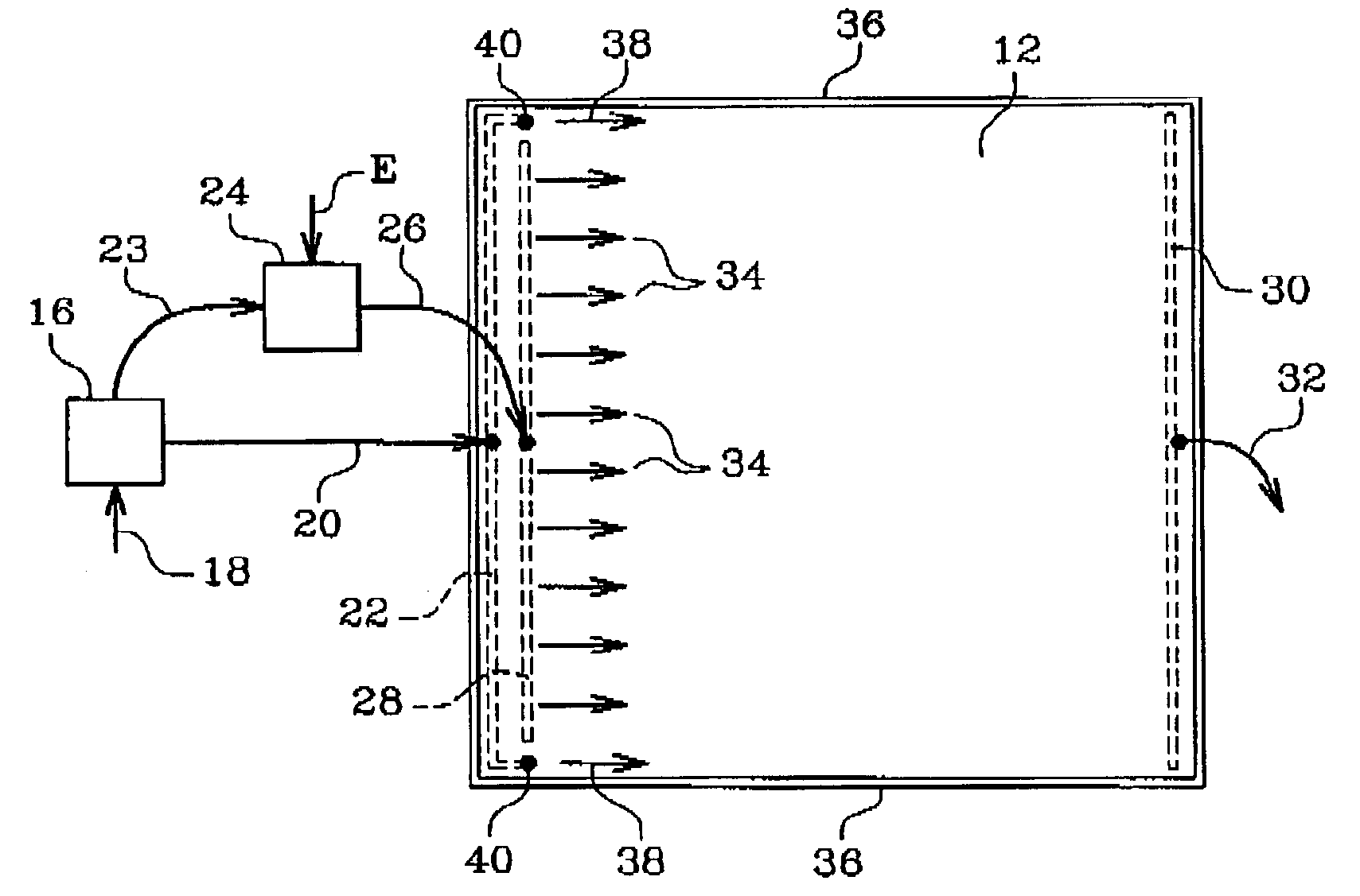
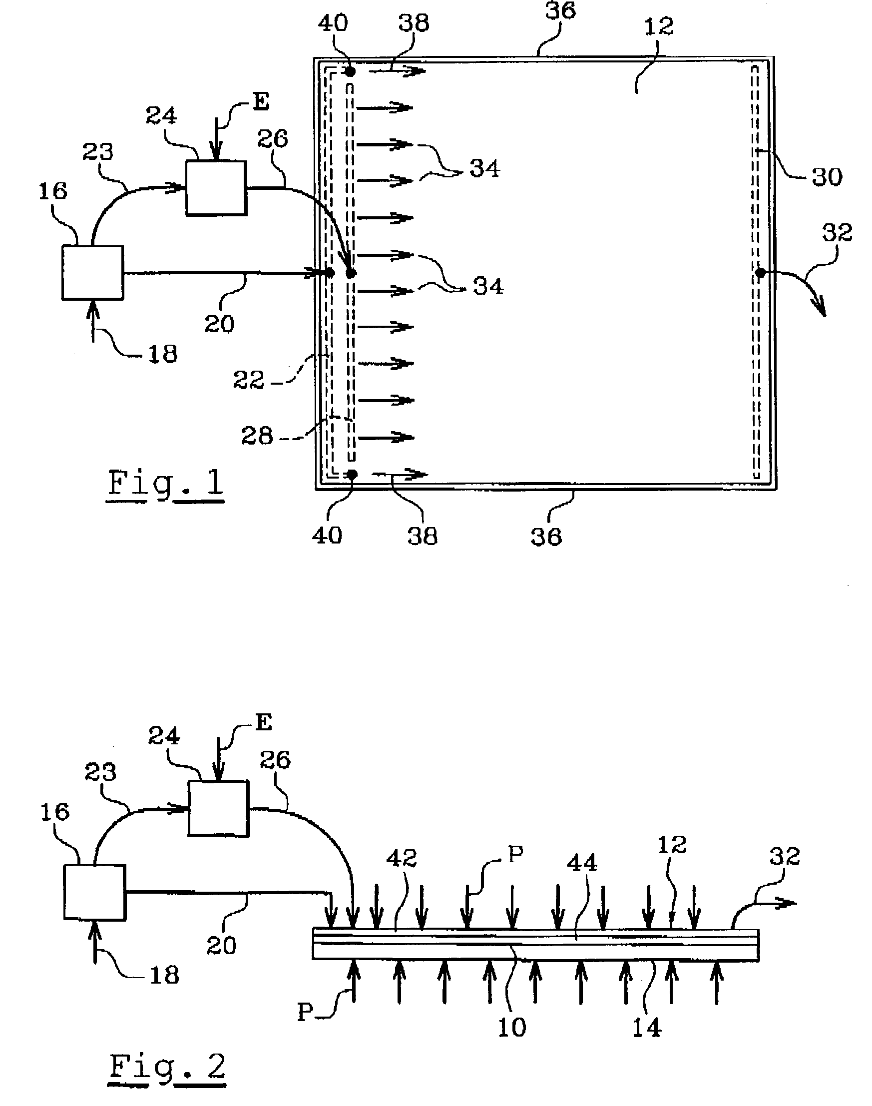
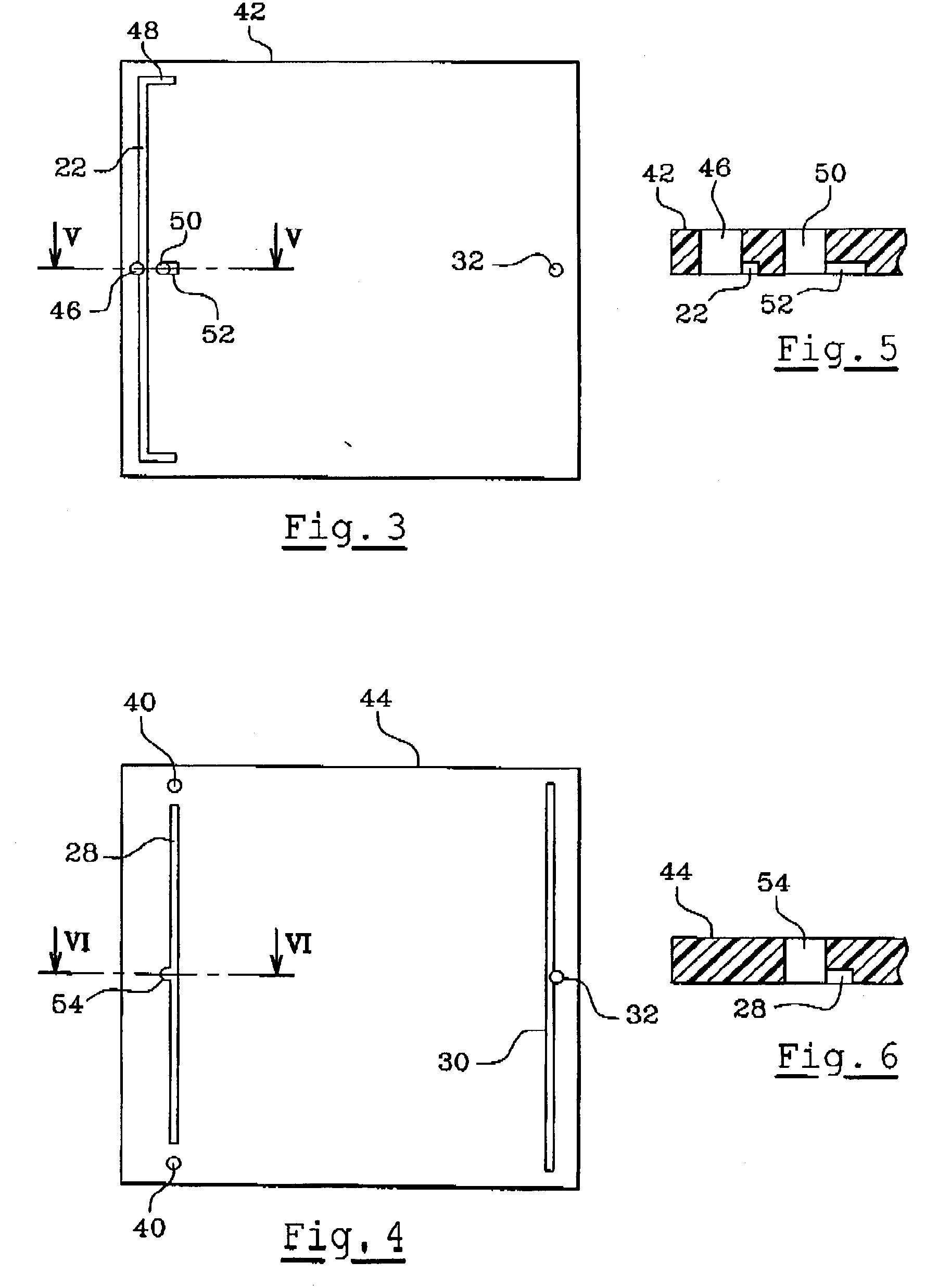
[0032] In FIGS. 1 to 6 which show apparatus having a single sample treatment path in highly simplified manner, reference 10 designates a stationary phase which is formed by a layer of material enclosed between two walls 12 and 14 made of a plastics material such as poly(tetrafluoroethylene), for example, with the stationary phase being constituted by monoliths of powder or particles of alumina, of silicate gel, of magnesium silicate, of cellulose, of polyamide, etc.

[0033] In preferred manner, the stationary phase 10 and the walls 12, 14 are in the form of a cartridge that is closed in leaktight manner, which cartridge is placed in an appropriate device enabling external pressure P to be exerted on its walls 12 and 14 as represented by arrows in FIG. 2, In a variant, the layer of stationary phase 10 may be placed inside a device which has the walls 12 and 14.

[0034] Means are associated with opposite longitudinal ends of the stationary phase 10 for the purposes of feeding it with movi...


PUM


Abstract

Apparatus for separating the components of a sample by OPLC type chromatography using liquid under pressure, the apparatus comprises a stationary phase forming one or more sample treatment paths and means for feeding moving phase to one end of the stationary phase, with means at the opposite end of the stationary phase for collecting moving phase, means for injecting moving phase also being provided at the sides of the stationary phase in order to eliminate edge effects in the fronts of sample components and in order to separate treatment paths from one another.

Description

[0001] The invention relates to apparatus for separating the components of a sample by liquid chromatography under pressure of the type known as "over pressured layer chromatography" or as "optimum performance layer chromatography" (OPLC).[0002] This technique consists in depositing a sample at one end of a layer of a stationary phase formed by a suitable material such as powder or particles of silica gel, alumina, magnesium silicate, cellulose, polyamide, etc., enclosed in leaktight manner between two walls so as to be subjected to an external pressure applied to said walls. The components of the sample are separated by being entrained through the stationary phase by means of a moving phase formed by a fluid under pressure. The walls defining the stationary phase are fitted with means for injecting the sample into the stationary phase and for feeding the stationary phase with the moving phase, said means being located at a first end of the stationary phase, and the walls are furthe...

Claims


Application Information

Patent Timeline
IPC IPC(8): G01N30/26G01N30/46G01N30/60G01N30/90G01N30/91G01N30/92
CPCG01N30/91G01N2030/906G01N30/6017
Inventor MINCSOVICS, EMILMANACH, MICHELKECSKES, LASZLOTAPA, BARNABASTYIHAK, ERNO
Owner BIONISIS SA
Why Eureka
Try Eureka