Zoom lens system

a zoom lens and lens technology, applied in the field of optical lens systems, can solve the problems of reducing optical power, impracticality large and difficult to correct, large front group, etc., and achieve the effects of strong impact, minimal cost of aspheric surface use, and generous tolerances

Active Publication Date: 2004-02-05
COURTLAND CAPITAL MARKET SERVICES LLC +1
View PDF17 Cites 55 Cited by
  • Summary
  • Abstract
  • Description
  • Claims
  • Application Information

AI Technical Summary

Benefits of technology

[0014] Summary of the Zoom Ratio Aspects of the Invention. The present invention overcomes the obstacles that currently limit zoom lens systems to a zoom ratio of about 101:1. The basic idea of the invention can be viewed as the use of a compound zoom lens system that consists of two separate zoom lens portions wherein the front zoom lens portion forms an intermediate image, and the rear zoom lens portion is a relay that transfers the intermediate image formed by the front zoom lens portion to the final image. The total zoom ratio of the complete compound zoom lens system is equal to the zoom ratio of the front zoom lens multiplied by the zoom ratio of the relay. Thus, if the zoom ratio of the front zoom lens portion is 20:1 and the zoom ratio of the relay is 15:1, then the zoom ratio of the entire compound zoom lens system is 300:1. The present invention can be used to achieve a zoom ratio of 300:1 or more, which greatly exceeds the practical limit of conventional zoom lens systems.
[0048] Thus, the front zoom lens portion need not be corrected for a simultaneously large intermediate image size and a large relative aperture (NA). Rather, it needs to be corrected for a large intermediate image size at a small aperture, and for a small intermediate image size at a large aperture. This makes the design of the front zoom lens portion considerably easier than the design of a traditional zoom lens system having the same zoom ratio as the front zoom lens system of the present invention.
[0050] As discussed above, in addition to a front zoom lens portion and a relay, the zoom lens systems of the invention preferably also include a pupil imaging unit. This unit serves to image the exit pupil of the front zoom lens portion into the entrance pupil of the relay. By selecting the appropriate powers, not only can the lens diameters, and attendant aberrations, of the relay be minimized, but control of the exit pupil position of the system can be improved.
[0056] The example of FIGS. 1-3 described above has a PNPP-PNPP construction in which the dash "-" signifies the end of the front zoom lens portion. Both the front zoom lens portion and rear zoom lens portion have variator and compensator zooming groups. One advantage of this configuration is that the intermediate image can be made absolutely stationary if desired. Rendering the image stationary will prevent it from passing through any optical surface that might reveal surface flaws and dust images that will appear at the final image. Using a four-group construction in the rear zoom lens portion also permits better control of the exit pupil position, which may be important for matching the telecentricity requirements of certain image sensors.
[0057] If movement of the intermediate image can be tolerated, then it is possible to eliminate one of the compensators. Removal of the rear compensator is preferred in this case because it only moves when the beam diameters are relatively small. The resulting construction will then be a PNPP-PNP configuration.
[0063] The existence of an intermediate image is common to all of these configurations, and this offers some unique opportunities for aberration correction that are not typically available in zoom lens system types of the prior art. For example, aspheric surfaces placed on elements located near the intermediate image can have a strong impact on distortion and other field aberrations without disturbing the spherical aberration correction. Advantages of placing an aspheric surface in this area include that the tolerances are generous because the beam diameters are small, and the elements themselves are small. This means that the cost of using aspheric surfaces in this region is minimal.

Problems solved by technology

As the zoom ratio is extended to about 100:1, however, the variator is required to change its object magnification to such an extent during zooming that aberrations become impracticably large and difficult to correct.
In addition, at such large zoom ratios there is a very large change in entrance pupil location during zooming, and this tends to make the front group very large and difficult to correct.
Another problem derives from the fact that, to reduce the aberration change that results from a large change of magnification, it is desirable that the variator have reduced optical powers.
Weaker optical power, however, also increases the lens travel and length of the optical system.
Since the requirements for either the front or the rear of the lens system can be satisfied, but not simultaneously, this results in no ideal place for the aperture stop.

Method used


Image

  • Zoom lens system
  • Zoom lens system
  • Zoom lens system

Examples


Embodiment Construction

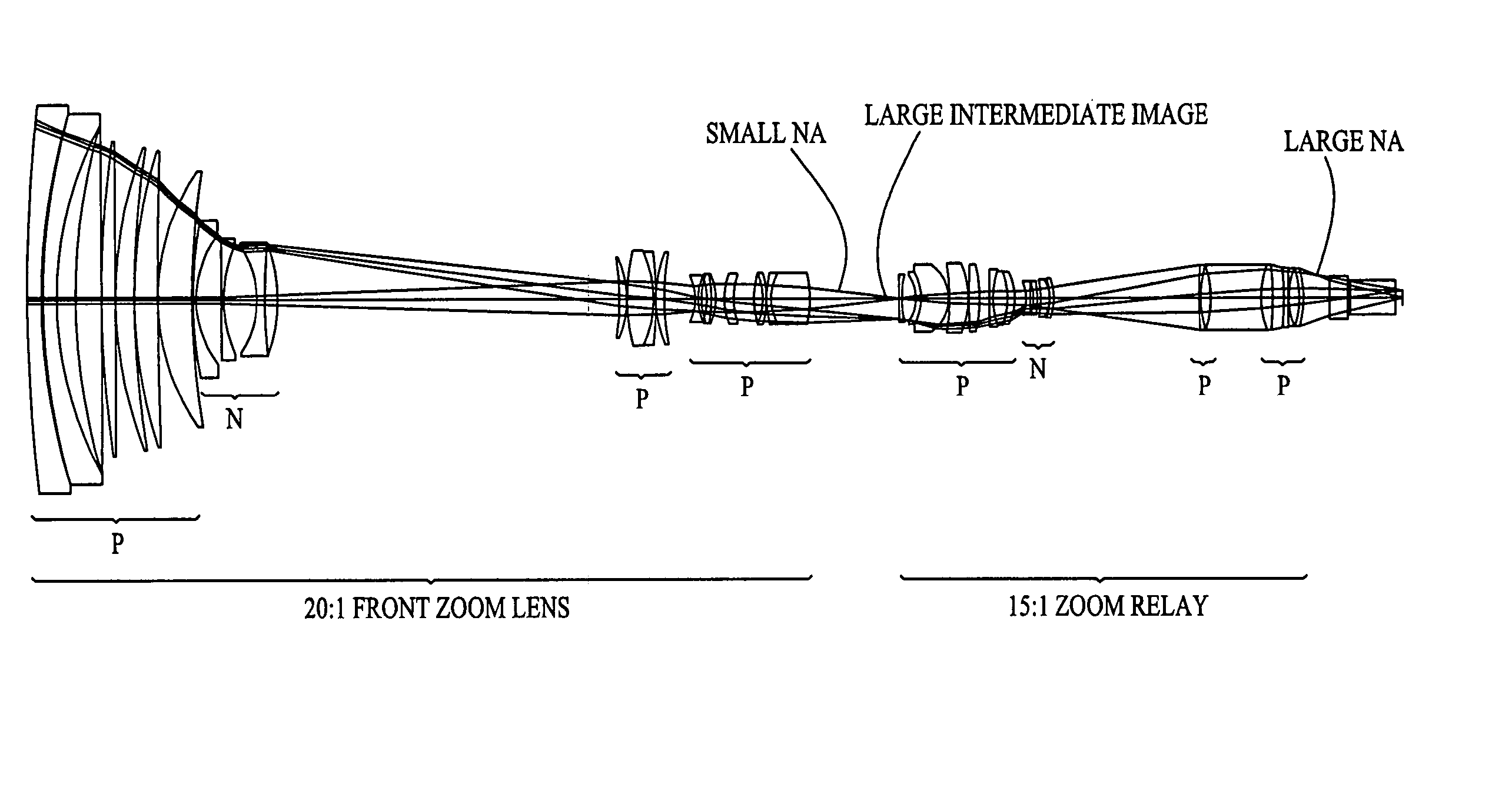
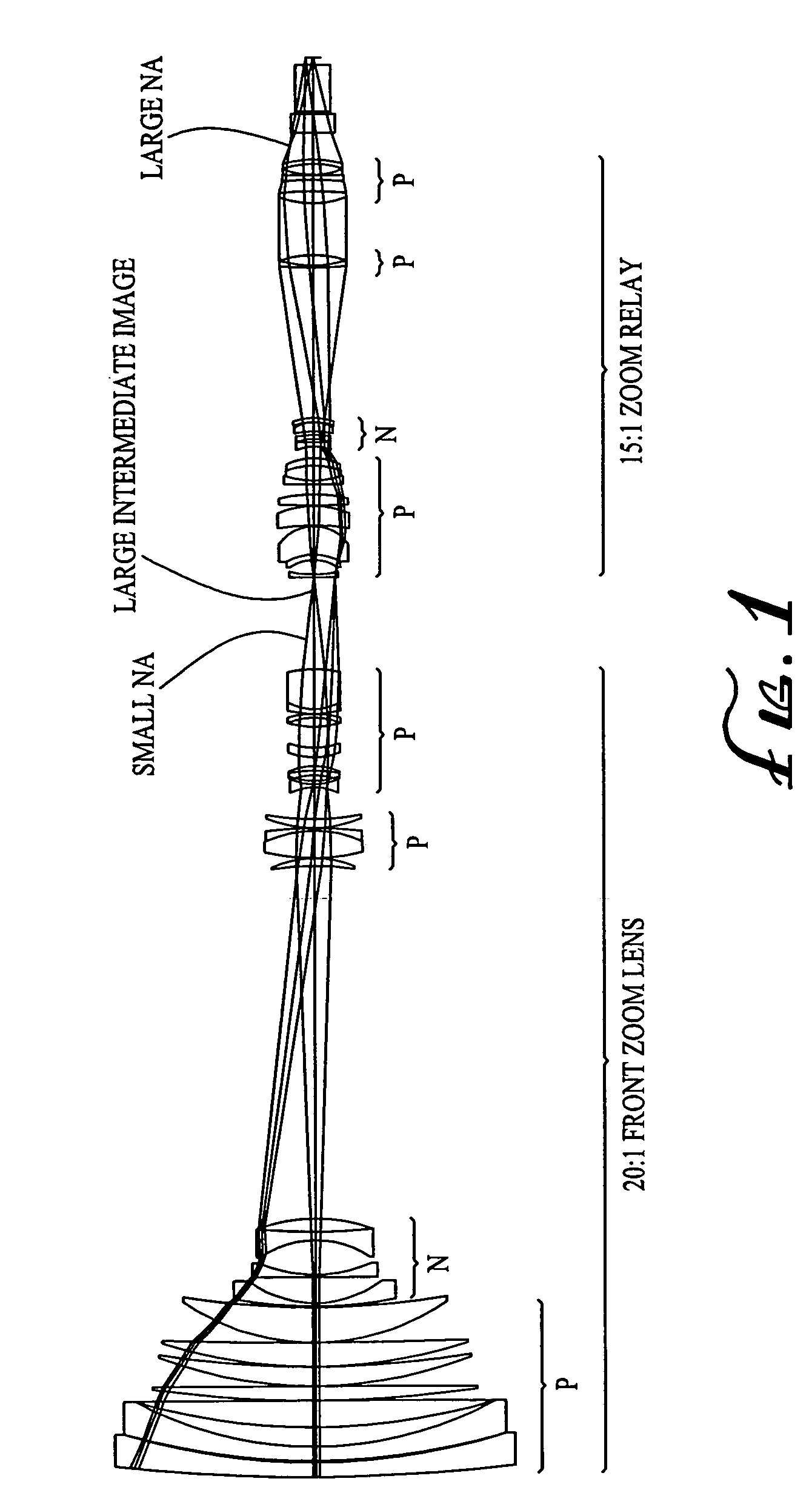
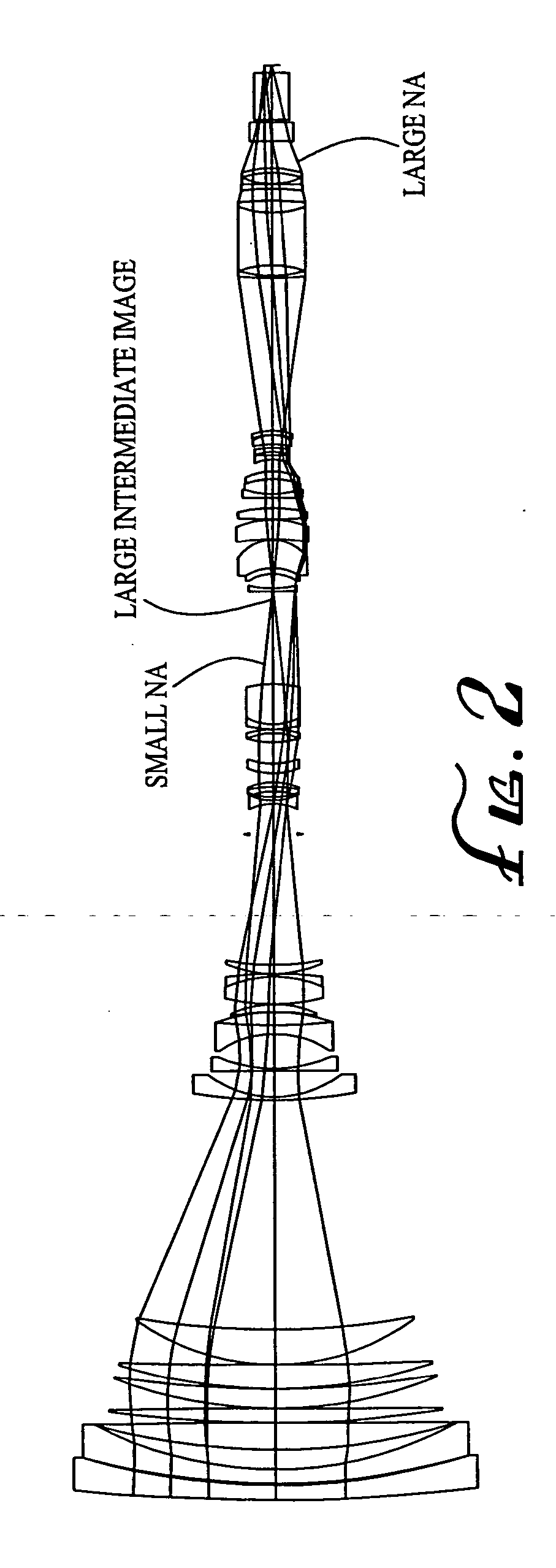
. As described above in the section entitled "Description of Some Zooming Principles and Systems of the Invention", each of the herein disclosed embodiments of the present invention includes a front zoom lens portion and a rear zoom lens portion thereby forming a compound zoom lens system. An intermediate image is formed after the front zoom lens portion whereby the rear zoom lens portion functions as a zoom relay to magnify the intermediate image so as to produce the magnified final image for capturing by film or any other kind of light detector or capture device, such as a charge coupled device (CCD), in a camera. For purposes of this application, the term "camera" is used generically to describe any kind of light detecting or capturing device that may be placed after the lens system of the present invention, including a still, video or movie capture device, whether containing film, videotape, optical disk, CMOS, CCD or another storage medium, or an eyepiece or the human eye. Any ...


PUM


Abstract

A zoom lens system is disclosed. The zoom lens system forms a final image of an object and a first intermediate real image between the object and the final image. The zoom lens system includes a first optical unit located between the object and the first intermediate real image. The first optical unit comprises at least one optical subunit which is moved to change the size (magnification) of the first intermediate real image. The zoom lens system also includes a second optical unit located between the first intermediate real image and the final image, at least a portion of which is moved to change the size (magnification) of the final image. The zoom lens system provides a wide zoom range of focal lengths with continuous zooming between the focal lengths and optional image stabilization.

Description

[0001] This application claims the benefit of U.S. Provisional Application No. 60 / 397,882, filed Jul. 22, 2002, which application is specifically incorporated herein, in its entirety, by reference.[0002] 1. Field of the Invention[0003] This invention relates to optical lens systems for cameras and other optical devices, and, in particular, to high performance zoom lens systems that produce a high quality image over a full zoom range of focal lengths and are capable of being provided with an extremely large zoom ratio.[0004] 2. Description of Related Art[0005] General Background of the Invention. The use of zoom lens systems for all types of photography, such as broadcast television, high definition television ("HDTV"), advanced television ("ATV"), video camcorders, film cinematography and still photography has become increasingly popular. As the use of zoom lens systems has increased, the demand for wider ranges of zooming capability, i.e. large zoom ratios, has also increased. For ...

Claims


Application Information

Patent Timeline
Patent Type & Authority Applications(United States)
IPC IPC(8): G02B15/14G02B15/16G02B15/173G02B27/64
CPCG02B13/14G02B15/12G02B27/646G02B15/173G02B15/161G02B15/142
Inventor BETENSKY, ELLIS I.CALDWELL, JAMES BRIANNEIL, IAIN A.YAMANASHI, TAKANORI
Owner COURTLAND CAPITAL MARKET SERVICES LLC
Why Eureka
Try Eureka