Laser welding processed

a technology of laser welding and processing, which is applied in the direction of welding apparatus, metal-working equipment, manufacturing tools, etc., can solve the problems of increasing the possibility of causing defects such as porosities, blowholes and cracks, and the frequency of output variations is not sufficient to prevent defects, so as to achieve the effect of efficiently preventing blowholes and cracks, and reducing the possibility of causing defects

Inactive Publication Date: 2004-02-12
NAT INST FOR MATERIALS SCI +1
View PDF1 Cites 30 Cited by
  • Summary
  • Abstract
  • Description
  • Claims
  • Application Information

AI Technical Summary

Benefits of technology

[0014] According to the present invention an described above, in the keyhole welding using a laser processor, weld defects such as porosities, blowholes and cracks can be efficiently prevented by introducing laser output variations with a frequency which conforms to a natural oscillation of a molten pool and a controlled waveform to thereby activate the p riodical flow of molten metal.

Problems solved by technology

The most significant problems arising when achieving the aforementioned object is that the difficulty increases in maintaining a keyhole stable b cause of an increas in the large p netr tion depth, and the possibility of causing defects such as porosities, blowholes, and cracks is thereby increased.
However, since a molten-pool natural oscillation frequency in not used for the frequency of the output variations, the frequency of the output variations does not activate the periodic flow of molten metal and is not sufficient to prevent defects in the de p-p n tration welding.
However, also in this case, defects occur according to a completely different occurrence mechanism of defects that are caused due to a high vapor pressure of zinc, and the object material and the penetration depth are peculiar.

Method used


Image

  • Laser welding processed
  • Laser welding processed
  • Laser welding processed

Examples


example 1

[0045] Partial penetration welding was performed on a steel plate SM490C which is for general welded structure by using a pulse-modulated CO.sub.2 laser beam. A He gas was used as a shielding gas, and side-shielding was perform d at a flow rate f 50 L / min.

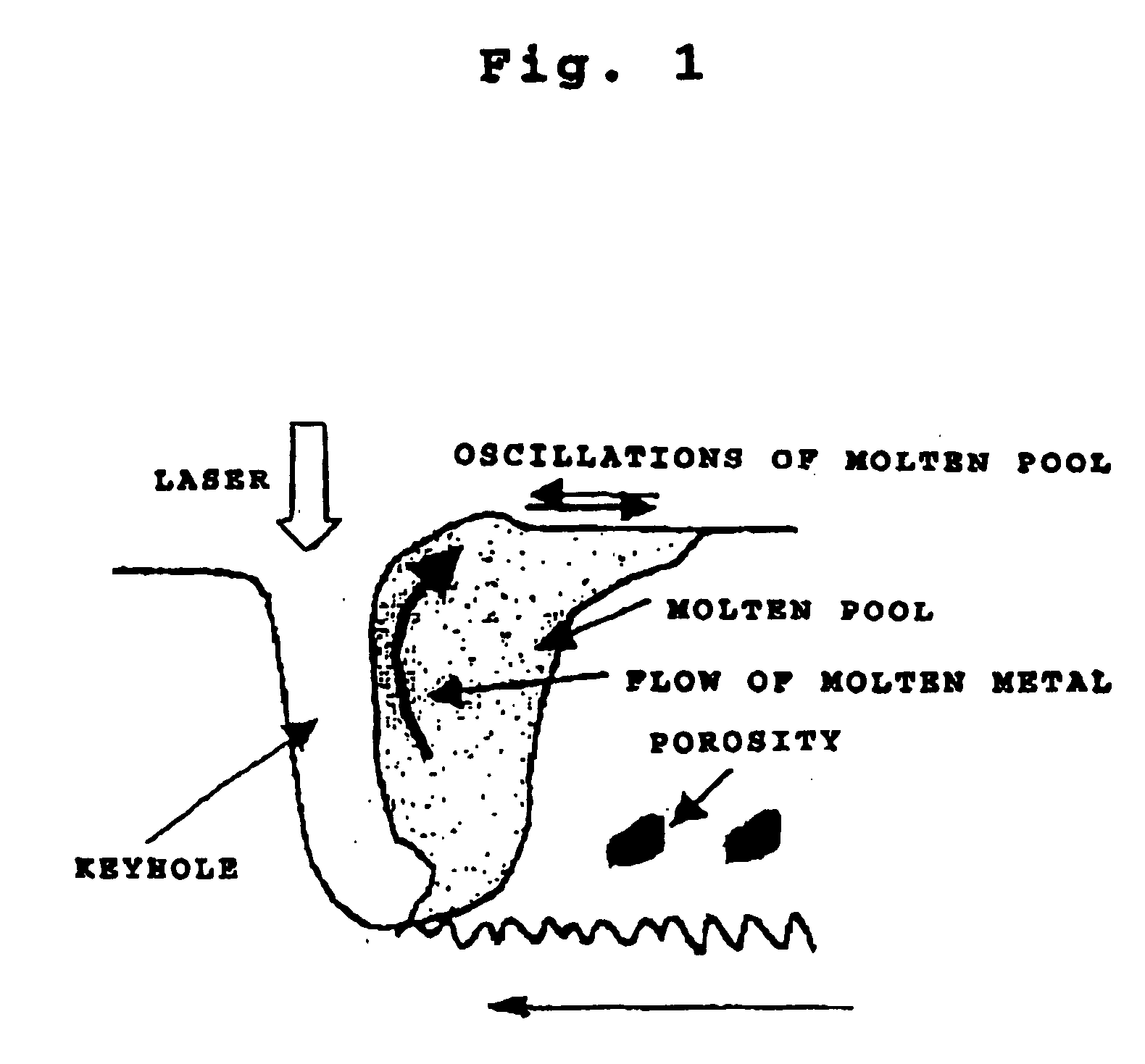
[0046] A r ctangular waveform as shown in FIG. 2 was us d for the output waveform; and the peak output WP was set to 20 kw, and the base output WN was set to 12 kW. Two types of duty cycles, namely a 50% duty cycle and a 70% duty cycle, were selected; and bead-on-plate welding was performed at various frequencies. Weld-defeat detection was performed by x-ray examinations with radiation emitted perpendicular to a laser beam axis and a weld line from a sideface of a weld test piece. The ratio (%) of the sum of detected defect areas to the area of molten metal is defined as a defect occurrence ratio Pr, and defect suppression effects were evaluated according to Pr. FIG. 5 shows the results of Pr m asurements performed at various frequ...

example 2

[0049] Partial penetration welding was p rformed on a steel plate SM490C which is for general welded structure by using a pulse-modulated CO.sub.2 laser beam. A He gas was used as a shielding gas, and side-shielding was performed at a flow rate of 50 L / min.

[0050] A trapezoidal waveform as shown in FIG. 4 was used for the output waveform; and the peak output WP war set to 20 kW, the bass output WB was set to 8 kw, and the rise time tu and the fall time td were varied. Bead-on-plate welding was performed with a 50% duty cycle. The penetration depth at this case was about 20 mm.

[0051] Weld-defect detection was performed by x-ray radiographies with radiation emitted perpendicular to a laser beam axis and a weld line from a sideface of a weld test piece. The ratio (%) of the sum of d tected defect areas to the area of molten metal is defined as a defect occurrence ratio Pr, and defect suppression effects were evaluated according to Pr.

[0052] FIG. 6 shows influences of the pulse rise time...


PUM

PropertyMeasurementUnit
flow rateaaaaaaaaaa
frequencyaaaaaaaaaa
frequencyaaaaaaaaaa

Abstract

In a laser welding method, occurrence of weld defects is effectively prevented, and a high-quality weld joint is provided; and in addition, a wide range of material processes including a laser-using de p-penetration welding technique can be implemented. In keyhole welding using a laser performing output pulse modulation, the welding is conducted in accordance with a frequency conforming to a natural fr queucy of a metal molten pool.

Description

[0001] The present invention relates to a laser welding method using a laser processor; more specifically, the invention relates to a new laser welding method capable of efficiently preventing weld defects in laser welding by introducing periodic waveform-controlled output variations to a pulse output to thereby activate a periodic flow of molten metal.[0002] In recent years, the development has rapidly progressed in the technology for increasing the output capacity of a laser oscillator, and the technology is expected to be applied to deep-penetration / high-speed welding.[0003] In this environment, the inventor has conducted studies and researches regarding low-heat-input / deep-penetration welding using a high-output-laser as an object of building a strong and tough structure.[0004] The most significant problems arising when achieving the aforementioned object is that the difficulty increases in maintaining a keyhole stable b cause of an increas in the large p netr tion depth, and th...

Claims


Application Information

Patent Timeline
Patent Type & Authority Applications(United States)
IPC IPC(8): B23K26/06B23K26/24
CPCB23K26/24B23K26/06
Inventor TSUKAMOTO, SUSUMUKAWAGUCHI, ISAOARAKANE, GOROHONDA, HIROSHI
Owner NAT INST FOR MATERIALS SCI
Why Eureka
Try Eureka