Disk device and method for controlling threshold value of disc device

Inactive Publication Date: 2004-02-19
SANYO ELECTRIC CO LTD
View PDF4 Cites 0 Cited by
  • Summary
  • Abstract
  • Description
  • Claims
  • Application Information

AI Technical Summary

Problems solved by technology

This results in the above-described execution/interruption of the recording process be

Method used


Image

  • Disk device and method for controlling threshold value of disc device
  • Disk device and method for controlling threshold value of disc device
  • Disk device and method for controlling threshold value of disc device

Examples


Embodiment Construction

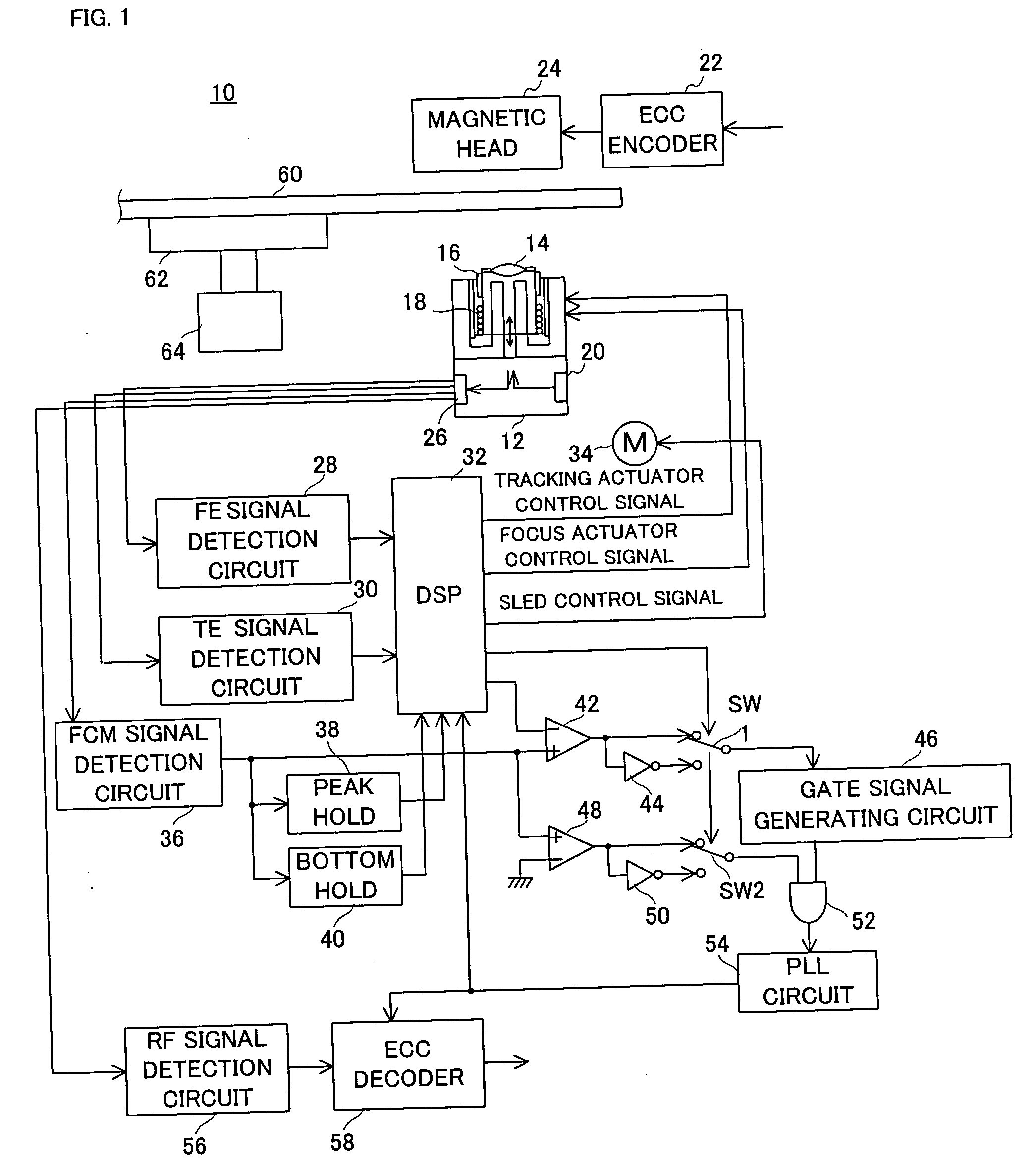
[0052] Referring to FIG. 1, an optical disk apparatus 10 of this embodiment includes an optical pick-up 12 formed with an optical lens 14. The optical lens 14 is supported by a tracking actuator 16 and a focus actuator 18. A laser beam radiated from a laser diode 20 is converged by the optical lens 14, and then incident upon a recording surface of a magnetooptical disk 60 such as an ASMO. At a time of recording, a pulse-modulated laser beam is radiated from the laser diode 20, and at a time of reproducing, a laser beam on which a high frequency is superimposed is radiated from the laser diode 20. In addition, at a time of the recording, a recording signal output from an ECC encoder 22 is applied to a magnetic head 24, and a magnetic field is put on the magnetooptical disk 60 by the magnetic head 42.

[0053] It is noted that the magnetooptical disk 60 is chucked to a spindle 62, and rotated by a spindle motor 64. A speed of rotation of the spindle motor 64 is decreased in proportion to...


PUM


Abstract

A disk apparatus (10) includes a spindle (62) to which a magnetooptical disk (60) is attached. An FCM is formed on the magnetooptical disk (60) along a track at intervals of a predetermined period, a laser beam having a different light amount depending on a time of an execution and an interruption of a recording process is incident upon the track. The FCM signal detection circuit (36) detects an FCM signal based on the laser beam reflected from the track, a comparator (42) compares a level of the FCM signal and a slice level, and a PLL circuit (54) generates a clock signal based on a comparison result by the comparator (42). When a change request between an execution/interruption of the recording process is applied, a predetermined first slice level is set to the comparator (42) until 200 mili seconds passes since a reception of the change request. When 200 mili seconds passes, a second slice level calculated based on a peak level of the FCM signal is set to the comparator (42).

Description

[0001] The present invention relates to a disk apparatus. More specifically, the present invention relates to a disk apparatus which rotates a disk recording medium formed with an emboss mark along a track in a predetermined period, and radiates onto the track a laser beam having a different light amount depending on a time of an execution and an interruption of a recording process, and detects an emboss mark signal associated with the emboss mark based on the laser beam reflected from the track.PRIOR ART[0002] In a magnetooptical disk such as an ASMO(Advanced storage Magneto Optical disk), an FCM (Fine Clock Mark) is formed in each predetermined period along a track. Thus, a level of the FCM signal, which is detected when a laser beam traces the FCM, is compared with a slice level (threshold value), and a clock signal is generated in a PLL system based on this comparison signal, then it becomes possible to easily control a rotation speed of a spindle motor, and a processing speed o...

Claims


Application Information

Patent Timeline
IPC IPC(8): G11B7/0045G11B20/14G11B7/005G11B7/007G11B11/105G11B27/24
CPCG11B7/0045G11B7/00718G11B7/24082G11B27/24G11B11/10595G11B20/1403G11B11/10578G11B11/105
Inventor MINECHIKA, SHIGEKAZU
Owner SANYO ELECTRIC CO LTD
Why Eureka
Try Eureka