Method and drive system for the control/regulation of linear pressure/cast movement

a technology of linear pressing/casting movement and drive system, which is applied in the direction of positive displacement liquid engine, mechanical apparatus, pumps, etc., can solve the problems of relative advantageous structural complexity, and achieve the effects of small increase complexity, high loss, and increased pressing/casting movement speed

Inactive Publication Date: 2004-02-19
PROCONTROL AG
View PDF9 Cites 23 Cited by
  • Summary
  • Abstract
  • Description
  • Claims
  • Application Information

AI Technical Summary

Benefits of technology

[0011] This invention is based on the object of finding a simple design for the drive for the pressing and / or casting axle, which will allow optimum control of the casting piston movement and an increase in the pressing / casting piston speed in comparison with the state of the art.
[0014] This novel invention has four very important advantages: with the simultaneous use of the pump and throttle for the return flow, it is possible to increase the speed of the pressing / casting movement with a relatively small increased complexity in terms of the design. The pump may thus be designed to be as small as possible and the throttle may be designed to be as large as necessary. This yields a relatively advantageous structural complexity. The throttle discharge, as a path subject to a very high loss, is used extremely briefly, and throttle losses are therefore minimized. Reference is made in this regard to European Patent 0 782 671. The pump may be used for energy recovery by way of the drive motor in the return flow because the motor and the pump can function as a generator.
[0015] In the forward movement, the pump may be used as a motor, and the energy obtainable via the server motor may be used for other axles and / or a portion may be stored in DC capacitors. The entire system may be used entirely or partially in the sense of an oscillator due to the fact that the largest possible energy component is only shifted back and forth in the system and is not destroyed. This novel invention makes it possible to utilize the acknowledged advantages of an electric drive essentially on larger machines with a closing force of more than 200 metric tons through a novel combination of servo motor and hydraulic system. All previous considerations regarding better control of the pressing or casting axle are concentrated largely on the back side of the piston and not on the rod side of the piston, with the goal of having even higher pressures act on the piston even more rapidly. This novel invention does not preclude the corresponding additional expenditures in terms of construction and control technology but it does make it possible to prevent them in many cases, and it solves the problem on the other side of the pressing or casting side and / or the piston rod side. A more rapid discharge of hydraulic oil on the piston rod side, which is also more demanding from the standpoint of control technology, is ensured, particularly in the phase of the greatest piston speed required. In the phase that is usually critical, this results in two oil flows, which are controlled at the highest level of the control / regulating technology. This makes it possible to select relatively small units for the individual components because they support one another mutually.
[0016] The surprising advantage, e.g., with respect to a largely dissipation-free design or a design without control valves, is that a small energy loss due to a valve subject to dissipation must be accepted during less than {fraction (1 / 10)}th of a second per casting cycle under some circumstances. Due to the reciprocal movement of the hydraulic medium on the back side of the piston and due to alternating use of the drive motor on the piston rod side, the drive motor may be used as a motor for the pump or as a generator (for the remaining period of time), as proposed in International Patent WO97 / 05387 and in European Patent 0 782 671, for example. It is also important that even in the case of an implementation that is subject to dissipation on the passive side of the drive, it is possible to prevent a load alternation in the hydraulic pump or in the coupling between the motor and the pump when there is a change in the direction of rotation of the pump. The accuracy of the control / regulation for the pump side is increased significantly.
[0017] This novel invention permits a large number of advantageous embodiments. Reference is made in this regard to claims 2 through 7 and 9 through 15. An especially advantageous embodiment is characterized in that the piston is driven for the forward movement either directly or indirectly by a gas, in particular nitrogen (N.sub.2) from a pressurized nitrogen tank through appropriate valves. The pump is designed as a fixed-volume pump, and the control / regulation of both the pump and the throttle valve is accomplished by way of a servo motor for each case. Both the pump and the throttle return flow are connected as a closed system to a closed and more or less pressureless oil container in the form of a pressure reservoir, corresponding to accumulator 9. A vacuum degassed oil is preferably used here. Traditional hydraulic oil, a chemical oil, or a mixture of water and glycol, for example, may be used as the hydraulic fluid. This novel invention offers the special advantage that it is possible to work with an extremely small amount of hydraulic fluid, e.g., on the order of 10 to 20 liters, whereas 100 to 200 liters are easily present in the system with the known designs. Another advantage is the extreme reduction in the risk of fire, thanks to the extremely small amount of hydraulic fluid.

Problems solved by technology

This yields a relatively advantageous structural complexity.

Method used


Image

  • Method and drive system for the control/regulation of linear pressure/cast movement
  • Method and drive system for the control/regulation of linear pressure/cast movement
  • Method and drive system for the control/regulation of linear pressure/cast movement

Examples


Embodiment Construction

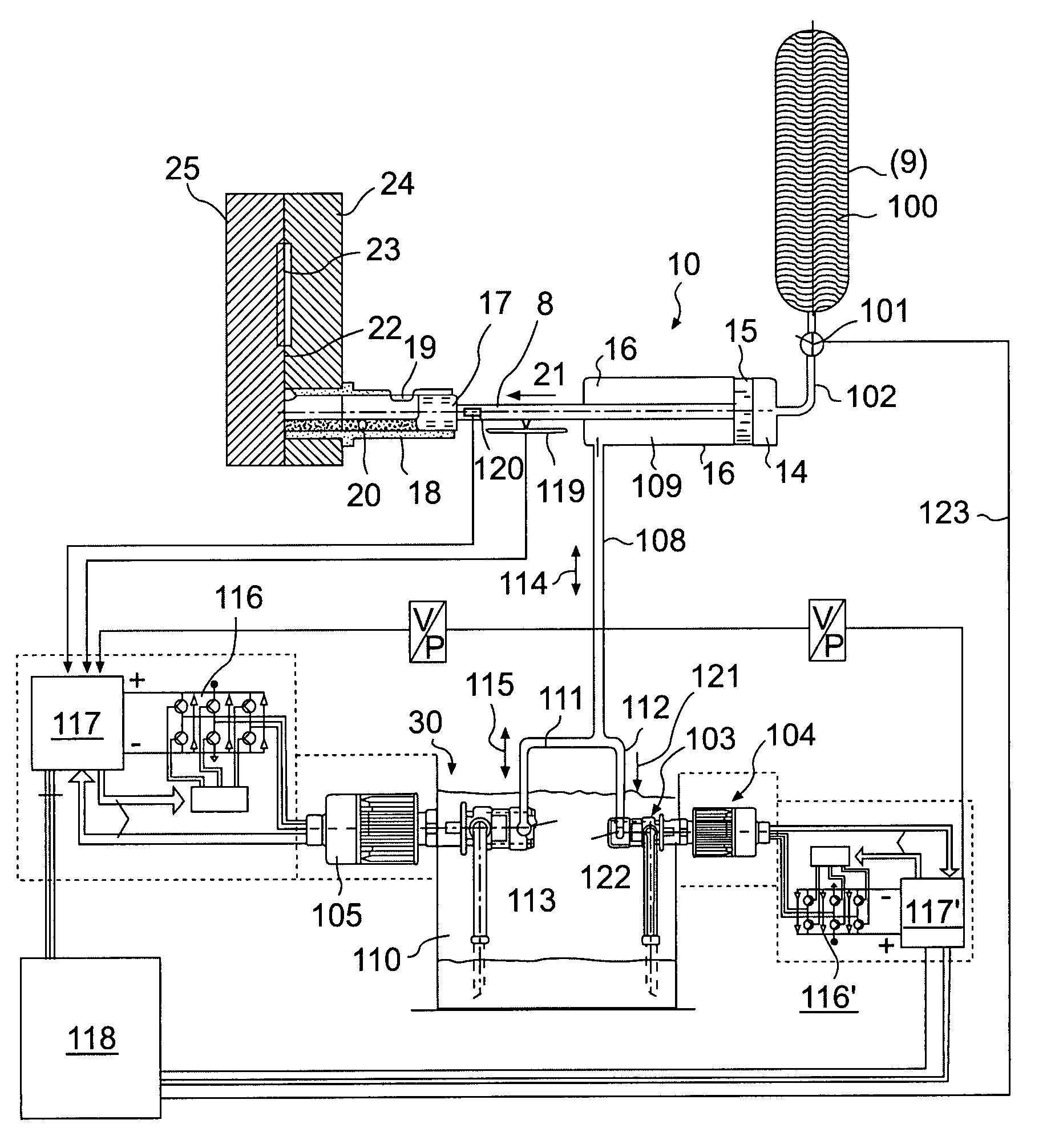
[0027] It can be seen in FIGS. 7 and 8 that the structural embodiment of the casting equipment is unchanged in comparison with the known designs. However, the elements for control of the oil flow on the piston rod side are designed according to a completely novel concept. A liquid medium, i.e., a hydraulic oil, is proposed as the medium on the piston rod side, circulating through a connecting line 108 / 111 between chamber 109 on the piston rod side of the casting driving cylinder 16 and a preferably closed tank 110. The oil flow passes through line 108 and is conveyed directly through a pump 30 and line 113. As indicated by the two arrows 114 and 15, the oil flow may go in one direction or the other as needed. Pump 30 is driven by a servo motor 105 and has the properties described in European Patent 782 671 and WO97 / 05387, for example. servo motors are characterized in particular by an electronic power unit 116 by which all the important parameters can be controlled virtually simulta...


PUM

PropertyMeasurementUnit
hydraulic pressureaaaaaaaaaa
pressureaaaaaaaaaa
speedaaaaaaaaaa

Abstract

The invention relates to a method for controlled driving of the cast axle (8) of pressure die casting machines, comprising a drive piston (15), wherein the forward and return motion of the piston (15) is carried out in a controlled manner. The invention is characterized in that the oil flow or oil pressure on the piston rod side is controlled / regulated by a pump (30) and additionally by a throttle valve (103) working in parallel at least during the filling phase, especially during the fast forward motion part.

Description

TECHNICAL SCOPE[0001] This invention relates to a method and a drive system for controlling / regulating the linear pressing / casting movement by means of a driving piston in injection molding machines and die-casting machines or presses, whereby a hydraulic medium is used at least on the drive side and / or the piston rod side.STATE OF THE ART[0002] In addition to the mold cavity, the compression axle or die-casting axle is essentially the heart of the die-casting machine or press. This is also true of cold or hot chamber magnesium die-casting machines. High injection forces and practical working casting rates of more than 3 m / sec to 5 m / sec are required. In the area of injection molding machines for use with plastics, machines that operate only with an electric drive have already become well established to a great extent, in addition to traditional machines driven by oil hydraulic systems. In cold and hot chamber magnesium die-casting machines, all the axles except the casting axle can...

Claims


Application Information

Patent Timeline
Patent Type & Authority Applications(United States)
IPC IPC(8): B22D17/32B29C45/82F15B1/02F15B11/044F15B15/14
CPCB22D17/32B30B15/163B29C2045/824B29C2945/76013B29C2945/76083B29C2945/76113B29C2945/762B29C2945/76381B29C2945/76498B29C2945/76598B29C2945/76678B29C2945/76785B29C2945/76859B29C2945/76862F15B1/02F15B11/044F15B15/1476F15B2211/20538F15B2211/212F15B2211/30525F15B2211/3144F15B2211/40515F15B2211/455F15B2211/50536F15B2211/5151F15B2211/6313F15B2211/7052F15B2211/76B29C45/82
Inventor STILLHARD, BRUNOSIEGRIST, RONALD
Owner PROCONTROL AG
Why Eureka
Try Eureka