

Plasma processing apparatus and method for asssembling the plasma processing apparatus
a technology of plasma processing apparatus and plasma, which is applied in the direction of plasma technique, energy-based chemical/physical/physico-chemical process, coating, etc., can solve the problems of high replacement cost and worn out
- Summary
- Abstract
- Description
- Claims
- Application Information
AI Technical Summary
Benefits of technology
Problems solved by technology
Method used
Image

Examples
Embodiment Construction
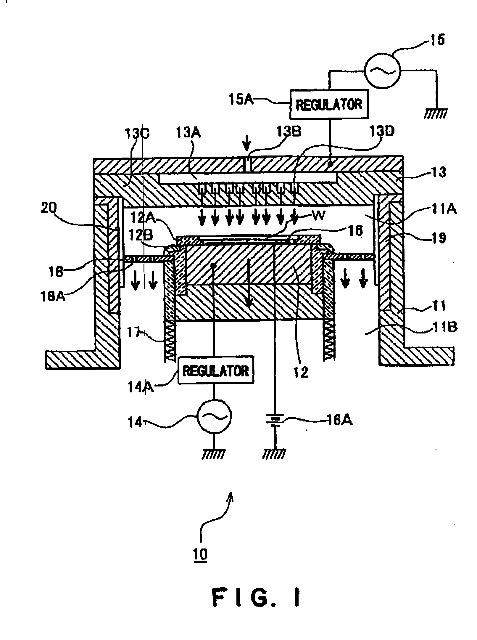
[0033] The present invention will be explained by means of embodiments shown in FIGS. 1 to 5.
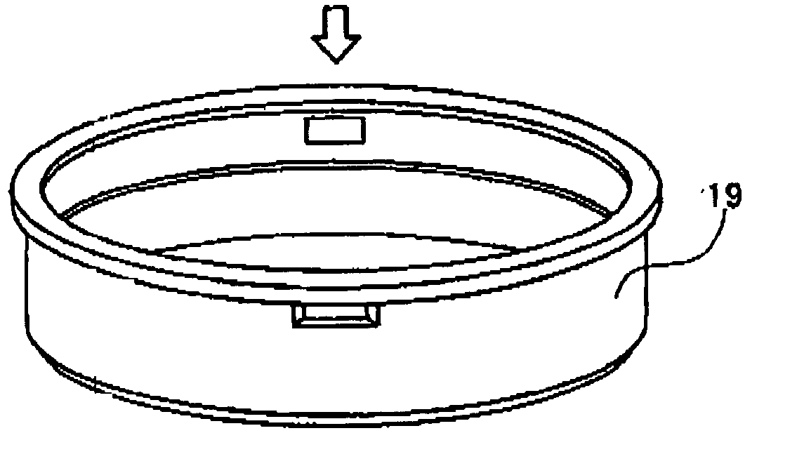
[0034] A plasma processing apparatus according to the embodiments shown in FIGS. 1 to 5, comprises, as exemplified in FIG. 1, a chamber 11, a lower electrode 12 for mounting a wafer in the chamber 11, which is movable up and down, and an upper electrode 13 disposed above the lower electrode 12 in parallel with the lower electrode 12, and has a fundamental structure based on the conventional plasma processing apparatus. The lower electrode 12 is connected to a high-frequency power source 14 for generating a bias via a regulator 14A. The upper electrode 13 is connected to a high-frequency power source 15 via a regulator 15A. An electrostatic chuck 16 is disposed on the surface of the lower electrode 12. The electrostatic chuck 16 is supplied with a high voltage by a d.c. source 16A and electrostatically attracts a wafer W.
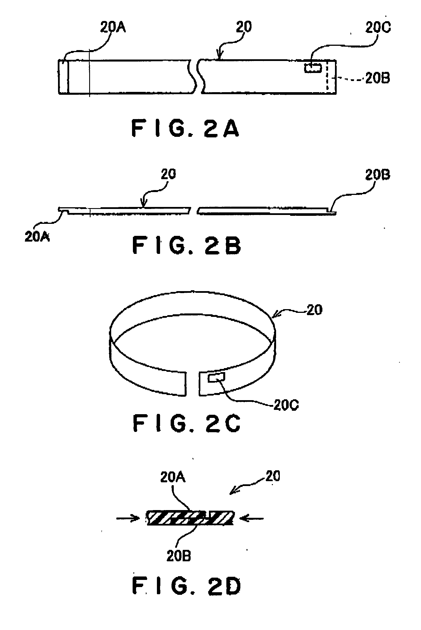
[0035] A focus ring 12A of ceramics, such as silicon carbide or others, ...
PUM
| Property | Measurement | Unit |
|---|---|---|
| Fraction | aaaaa | aaaaa |
| Fraction | aaaaa | aaaaa |
| Length | aaaaa | aaaaa |
Abstract
Description
Claims
Application Information