Optical pickup apparatus and optical element

a pickup apparatus and optical element technology, applied in the field of optical pickup apparatus and optical element, can solve the problems of inability to conduct reproducing and recording information, inability to achieve optical performance, and insufficient physical recording density, so as to achieve the effect of reducing the number of parts

Inactive Publication Date: 2004-03-11
KONICA CORP
View PDF5 Cites 131 Cited by
  • Summary
  • Abstract
  • Description
  • Claims
  • Application Information

AI Technical Summary

Benefits of technology

[0042] An object of the invention is to provide an optical pickup device and an optical element to be used for reproducing and / or recording of information for three types of optical information recording media each having a different wavelength and a different protective substrate thickness wherein the aforementioned problems are taken into consideration, various types of aberrations are inhibited, and the number of parts can be reduced.

Problems solved by technology

In that case, properties required as an optical system are relatively generous, though physical recording density is not improved substantially.
Therefore, even if a light source having the same wavelength is used, it is not possible to conduct reproducing and recording of information by using the same optical pickup device simply.
However, there is a fear that optical performances are not attained when an objective optical element is made to have various optical functions, although it is preferable for reduction of the number of parts, low cost and downsizing.
When attaining the compatibility for three formats which is to be solved this time, it is impossible to solve by using simply the aforesaid methods, because of many objects to be corrected.
If a difference of working distances is great, a load on an actuator is increased, and power consumption is also increased.
Therefore, for example, an optical path for light with each of the first-third wavelengths is different from others, and therefore, a plurality of optical elements are required to be arranged so that each of them may correspond to each optical path, and thereby, there have been problems that a structure of an optical disc device is complicated and the number of parts of the apparatus is increased.
Further, there have been problems that image height characteristics are worsened and various aberrations such as coma and astigmatism are caused, in the case of tracking to move an objective lens for an optical disc when conducting reproducing and recording for the optical disc, because divergent light enters the objective lens.
There has further been a problem that spherical aberration caused by temperature changes is greater, compared with the so-called apparatus of an infinity system type wherein parallel light enters an objective lens.

Method used


Image

  • Optical pickup apparatus and optical element
  • Optical pickup apparatus and optical element
  • Optical pickup apparatus and optical element

Examples


Embodiment Construction

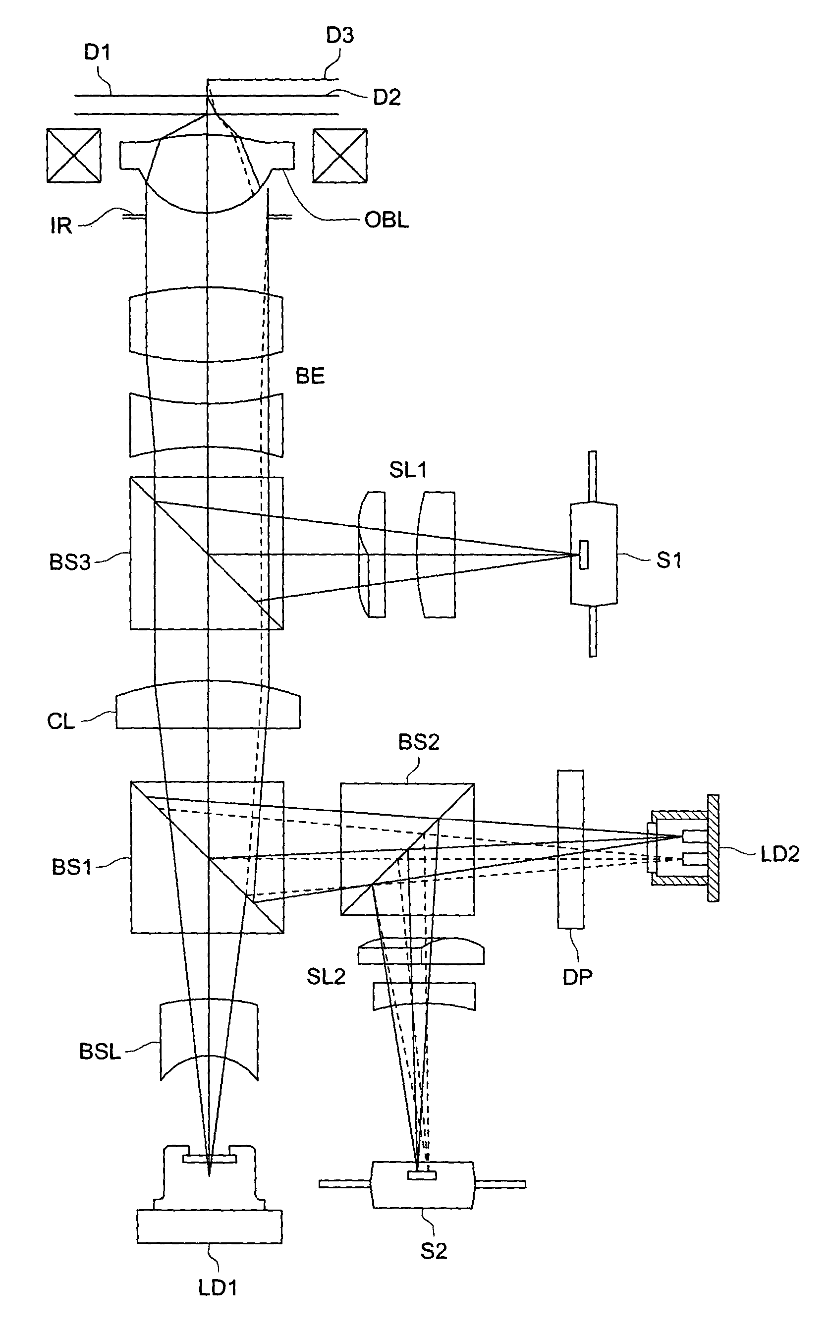
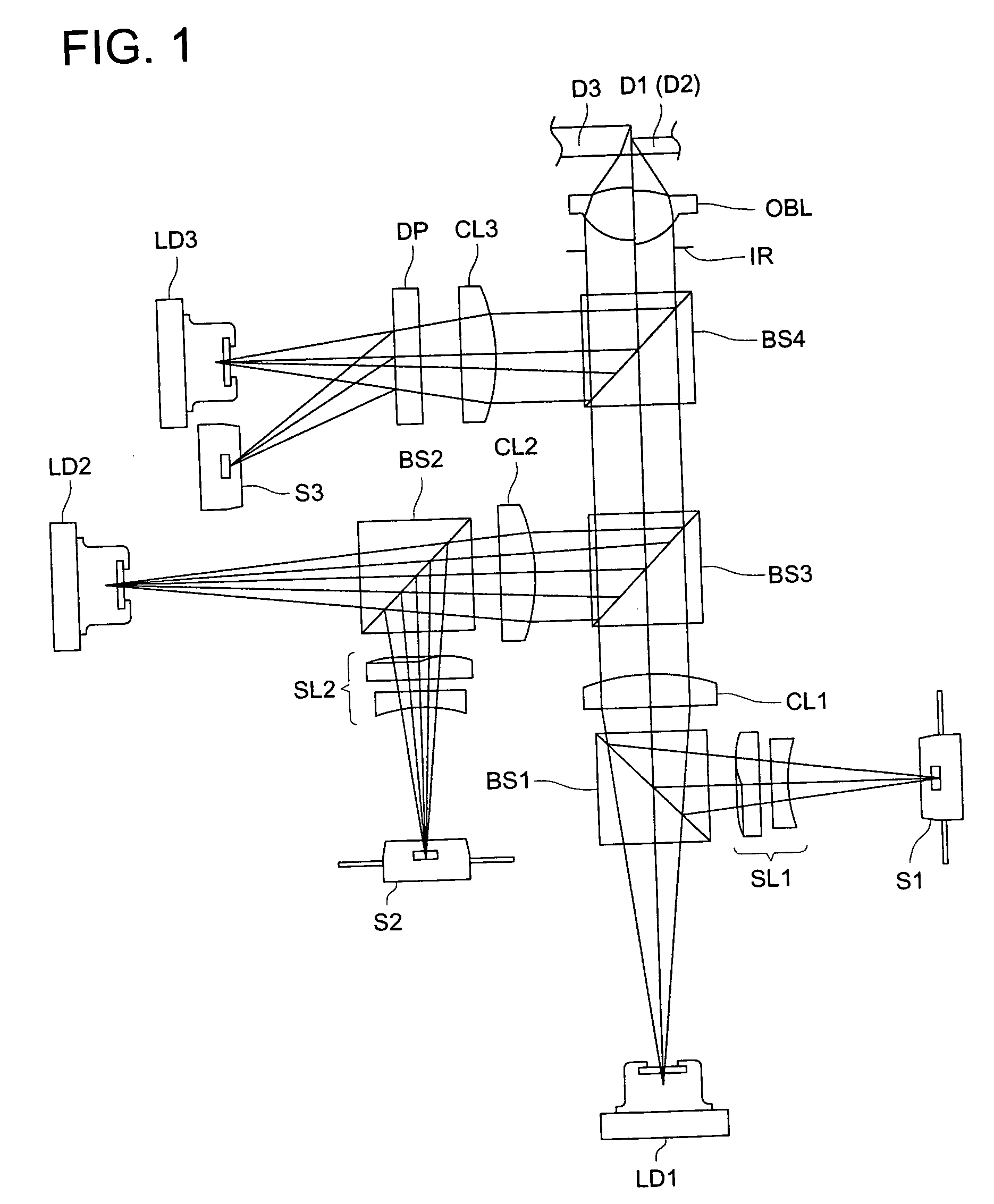
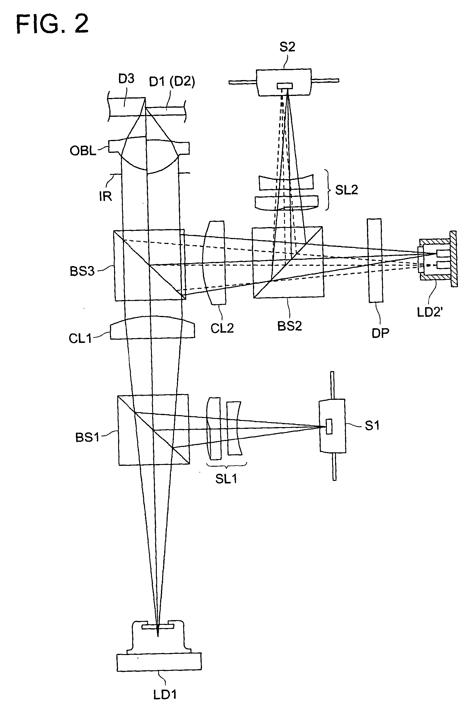
[0626] Next, the first example of the optical pickup device and the optical element shown in the aforementioned embodiment will be explained.

[0627] In the present example, let it be assumed to use an objective lens wherein surface S1 and surface S2 are combined on the plane of incidence side such as that shown in FIG. 8.

[0628] To be concrete in explanation, a plane of incidence of an objective lens representing a single and two-sided aspheric lens is divided into No. 2 surface whose height h from optical axis L is 1.45 mm or more, No. 2' surface whose height is not less than 1.1 mm and is less than 1.45 mm and No. 2" whose height is less than 1.1 mm, as shown in FIG. 14.

[0629] On No. 2' surface and No. 2" surface, there are formed plural serrated and discontinuous diffracting ring-shaped zones 80 having substantial inclination for an optical surface in a form of a prescribed aspheric surface, and on the optical surface of each diffracting ring-shaped zone 80, there is formed optical...


PUM

PropertyMeasurementUnit
wavelength λ3aaaaaaaaaa
wavelengthaaaaaaaaaa
thicknessaaaaaaaaaa

Abstract

An optical pickup apparatus comprises first, second and third light sources to emit light fluxes of wavelength lambda1, lambda2 and lambda3 for conducting recording and / or reproducing information for first, second and third optical information recording mediums having respective protective substrates of thickness t1, t2 and t3 and a diffractive optical element located on a common optical path for the first, second and third light sources. A converged-light spot is formed on the first optical information recording medium with m-th order diffracted-light ray of the wavelength lambda1, on the second optical information recording medium with n-th order diffracted-light ray of the wavelength lambda2, and on the third optical information recording medium with k-th order diffracted-light ray of the wavelength lambda3 generated by the diffractive optical element respectively, wherein one of m, n and k is different from one of other two numbers.

Description

[0001] The present invention relates to an optical pickup device and to an objective optical element used for the optical pickup device, and in particular, to an optical pickup device complying with standards of a plurality of optical information recording media (optical discs) and to an objective optical element used for the optical pickup device.[0002] Up to the present, there have been developed and manufactured optical pickup devices (which are also called optical heads or optical head devices) for conducting reproducing and recording of information for optical information recording media (which are also called optical discs or media) such as CD (compact disc) and DVD (digital video disc or digital versatile disc), and they have come into wide use generally.[0003] In recent years, there have been made studies and developments for standards of optical information recording media which make high density information recording possible.[0004] The optical pickup device of this kind c...

Claims


Application Information

Patent Timeline
Patent Type & Authority Applications(United States)
IPC IPC(8): G11B7/00G11B7/125G11B7/135
CPCG11B7/1275G11B7/1353G11B2007/0006G11B7/1392G11B7/1374
Inventor IKENAKA, KIYONOATARASHI, YUICHI
Owner KONICA CORP
Why Eureka
Try Eureka