Easy-to-install, mechanically-operated automatic/manual device for controlling an outlet for water or any fluid

a mechanical operation and manual device technology, applied in the direction of operating means/releasing devices of valves, stoves or ranges, lighting and heating apparatus, etc., can solve the problems of obstructing the functioning of drain valves, obstructing the operation of drain valves, and inadequate electronic valves, so as to avoid water wastage, facilitate installation, and allow the effect of water system

Inactive Publication Date: 2004-03-18
CHAVARRIA ANA LIDIETH MADRIGAL
View PDF5 Cites 15 Cited by
  • Summary
  • Abstract
  • Description
  • Claims
  • Application Information

AI Technical Summary

Benefits of technology

[0001] The primary objective of the invention is to provide, to all users of potable water service supplied by the service provider company, a device that installs easily and allows use of the water system without having to be present while filling up containers, tanks, troughs, barrels, tubs, bathtubs, toilets, pools, and reservoirs in general, with the security that once the desired water level is reached the flow will be stopped, thus making unnecessary the presence of a person to start or stop the flow of water. A secondary objective of the invention is to provide a device that avoids wastage of water due to forgetfulness, by functioning totally and completely as a seal against any non-required passage of the vital liquid or once the container in question has been filled. A third and no less important objective of this invention is to provide to all homes and places where the water supply is scarce and only available for a few hours, most often at night, a low-cost device that allows people to not neglect their other activities or physiological needs, such as nighttime rest, in order to tend to the filling of containers necessary for their daily consumption and needs.PREVIOUS TECHNIQUE
[0002] There exist many simple fluid control systems that use relatively cheap components. One example of control by feedback is a drinking trough that uses a float to determine the water level. When the water level falls below a set point, the float drops, opens a valve, and allows more water into the trough. When the water level rises the float also rises, and upon reaching a certain point the valve is closed and the water flow is cut off. The disadvantage of this float flow valve is that the valve seat progressively gets worn down by the water pressure, and after a short time needs to be replaced. In the device represented by this invention there is no wearing down of the valve seat, it functions by totally opening or shutting off the flow of water of any other liquid. Another example is U.S. Pat. No. 4,094,327, which is a valve for toilet tanks. Said valve is supported inside the tank at the water inflow point as a vertical column. There exist simpler systems as well, which use a rod with a copper or plastic ball at the end that acts as a float. All such systems in many cases obstruct the functioning of the drain valve. This invention is installed outside the tank, and thus the drain valve remains inside the tank without obstructions. Another example is U.S. Pat. No. 4,566,484, in which, the valve is submerged within the liquid. This invention is installed on the side of the tank to be filled. Another example is ES 2 096 539, which is a storage tank shutoff valve. Said control valve uses two tubes and more complex mechanisms. This invention is installed outside of the tank and uses only one tube, which conducts the fluid. Consequently, this invention substitutes for any complex mechanism used to substitute an electronic valve. An electronic valve is inadequate in some cases, such as where flammable fuels are present, or in the case of vessels or bathtubs were a person will be immersed in the water. An electronic valve is controlled by an electric or electronic water-level guard and electrodes that detect high or low water level. This invention has the functions and simple mechanisms of an electronic valve. In order to fulfill the aforementioned objectives and others, this invention is a device that can be easily installed at an outflow of water or any other liquid, with mechanical functioning that neither needs nor uses any source of electric or electronic energy, rechargeable or standard batteries, solar energy, nor any other power source mechanism, in order to fill any kind of containers, tanks, troughs, barrels, tubs, bathtubs, toilets, pools, reservoirs, or similar vessels, either automatically or manually, including the ability to connect it to any garden hose or other type of hose.

Problems solved by technology

The disadvantage of this float flow valve is that the valve seat progressively gets worn down by the water pressure, and after a short time needs to be replaced.
All such systems in many cases obstruct the functioning of the drain valve.
An electronic valve is inadequate in some cases, such as where flammable fuels are present, or in the case of vessels or bathtubs were a person will be immersed in the water.

Method used


Image

  • Easy-to-install, mechanically-operated automatic/manual device for controlling an outlet for water or any fluid
  • Easy-to-install, mechanically-operated automatic/manual device for controlling an outlet for water or any fluid
  • Easy-to-install, mechanically-operated automatic/manual device for controlling an outlet for water or any fluid

Examples


Embodiment Construction

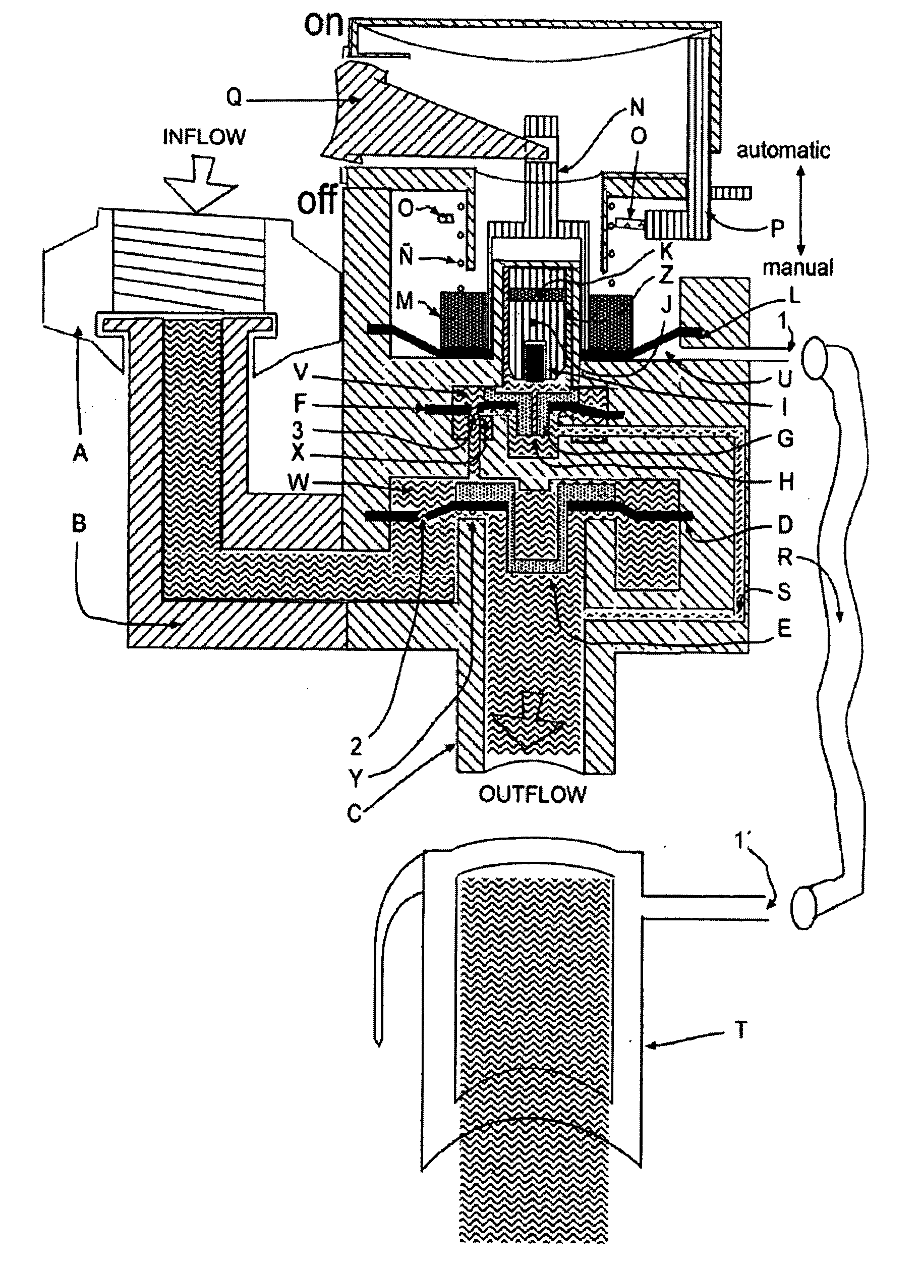
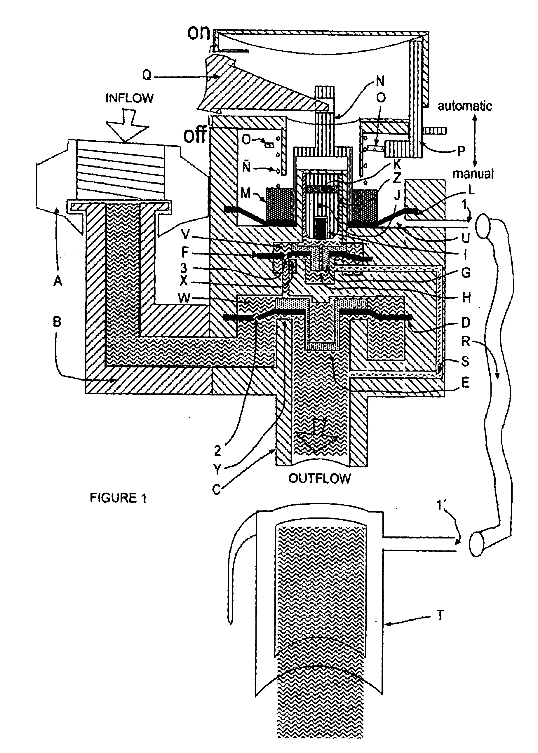
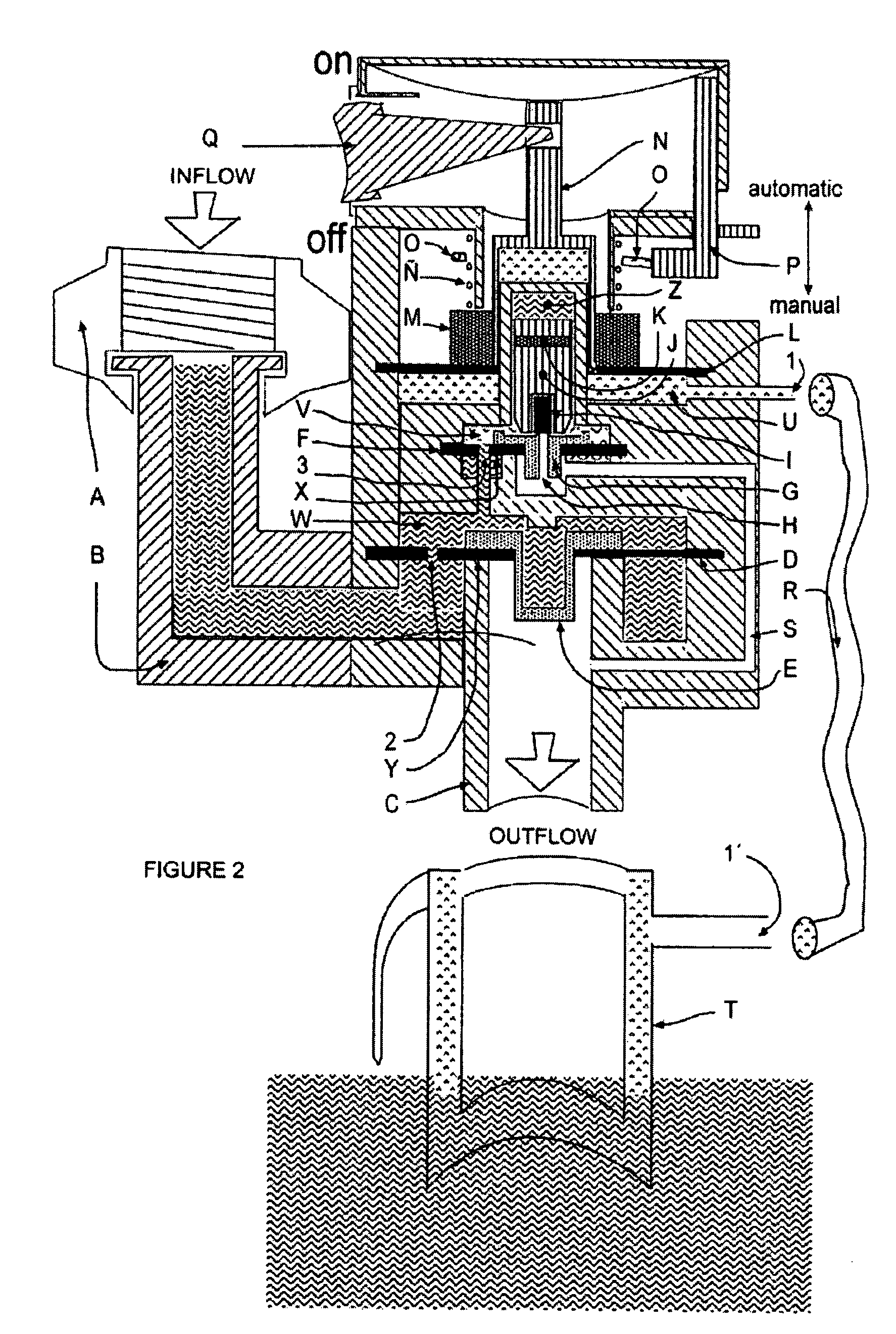
[0010] The Automatic / Manual Device for Controlling Outflow of Water or any Fluid, with Mechanical Functioning and Easy Installation, is comprised of the part A dedicated to the admission or inflow of the water or other fluid, as can be noted in FIG. 1, where A is the stream inflow with a threadable end and arm B, which can be pointed in whatever direction is desired, attached to the device housing C. Duct B for the passage of water or other fluid leads to pressure chamber W, which houses the first rubber membrane D, which has a small diametric orifice 2. Its lateral portion communicates with pressure chamber V and cylinder Z. Pressure chamber V houses the second rubber membrane F, which has a small diametric orifice 3. The second rubber membrane F is supported by part G, which in turn has a small orifice H. Cylinder Z houses piston J. Piston J houses small magnet K and rubber stopper I, with rubber stopper I being situated at its external lower end, for purposes of plugging the smal...


PUM


Abstract

This invention refers to an Automatic / Manual Device for Controlling Outflow of Water or any Fluid, with Mechanical Functioning and Easy Installation. It has a threadable intake nozzle for the inflow of water or any other fluid. The nozzle can be turned to direct the device as needed. Also, in the interior of the device there are two magnets with inverse polarity, a spring, two rubber membranes with orifices, a rubber membrane without an orifice, two supports for said membranes an air chamber, a manually-activated metal ring, a functioning mechanism with the following positions: ON-OFF, a double copper tube that is submerged in the container to be filled, a rubber hose connecting the double copper tube with the air chamber, and an activating mechanism with "manual", and "automatic" positions for operating the device. The functioning of this invention is provided for, with the objective being to shut off the flow of water or any other fluid once the container, tank, trough, barrel, tub, bathtub. toilet, pool, or other reservoir has been filled, by way of hydrostatic pressure exerted by the water container itself through the double copper tube connected to the air chamber by way of the rubber hose, with the necessary pressure being exerted to separate the magnets and thus close the fluid flow orifice.

Description

OBJECTIVE AND DESCRIPTION OF THE INVENTION[0001] The primary objective of the invention is to provide, to all users of potable water service supplied by the service provider company, a device that installs easily and allows use of the water system without having to be present while filling up containers, tanks, troughs, barrels, tubs, bathtubs, toilets, pools, and reservoirs in general, with the security that once the desired water level is reached the flow will be stopped, thus making unnecessary the presence of a person to start or stop the flow of water. A secondary objective of the invention is to provide a device that avoids wastage of water due to forgetfulness, by functioning totally and completely as a seal against any non-required passage of the vital liquid or once the container in question has been filled. A third and no less important objective of this invention is to provide to all homes and places where the water supply is scarce and only available for a few hours, mos...

Claims


Application Information

Patent Timeline
Patent Type & Authority Applications(United States)
IPC IPC(8): F16K21/18F16K21/20F16K31/40
CPCF16K31/404F16K21/18Y10T137/7297Y10T137/7501Y10T137/73
Inventor SOSA, RAFAEL H.T.
Owner CHAVARRIA ANA LIDIETH MADRIGAL
Why Eureka
Try Eureka