
Filter for cooling water in a light water cooled nuclear reactor

Inactive Publication Date: 2004-04-22
WESTINGHOUSE ELECTRIC SWEDEN
View PDF8 Cites 24 Cited by
  • Summary
  • Abstract
  • Description
  • Claims
  • Application Information

AI Technical Summary

Benefits of technology

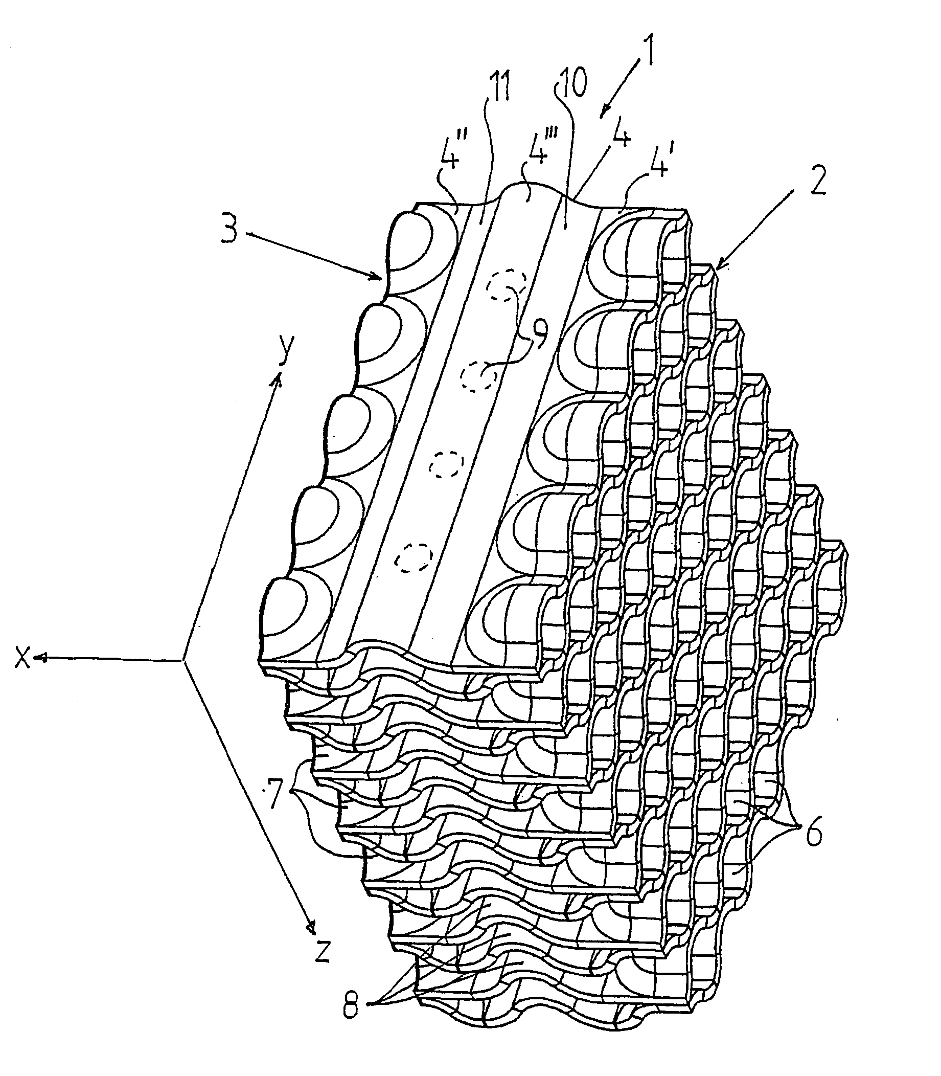
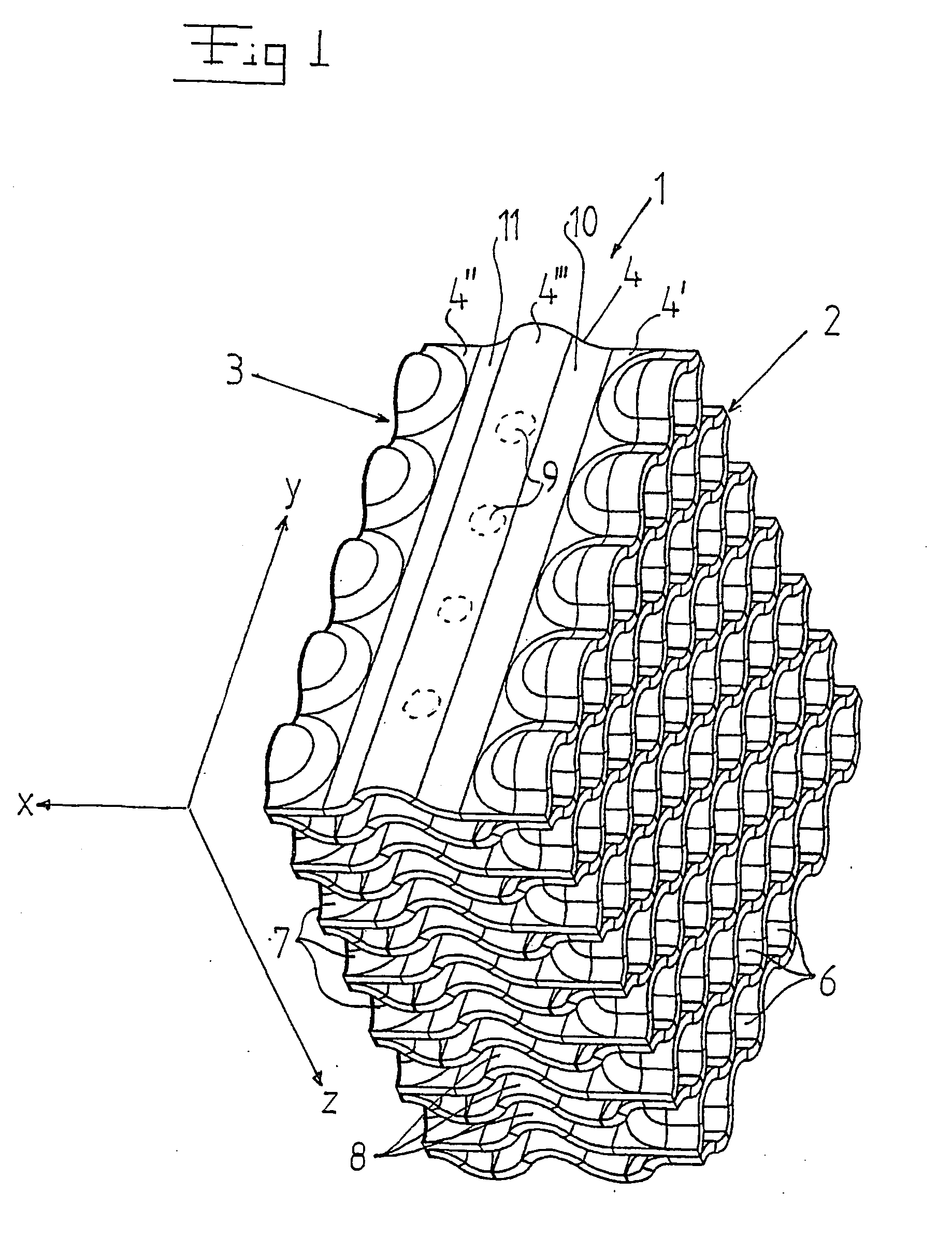
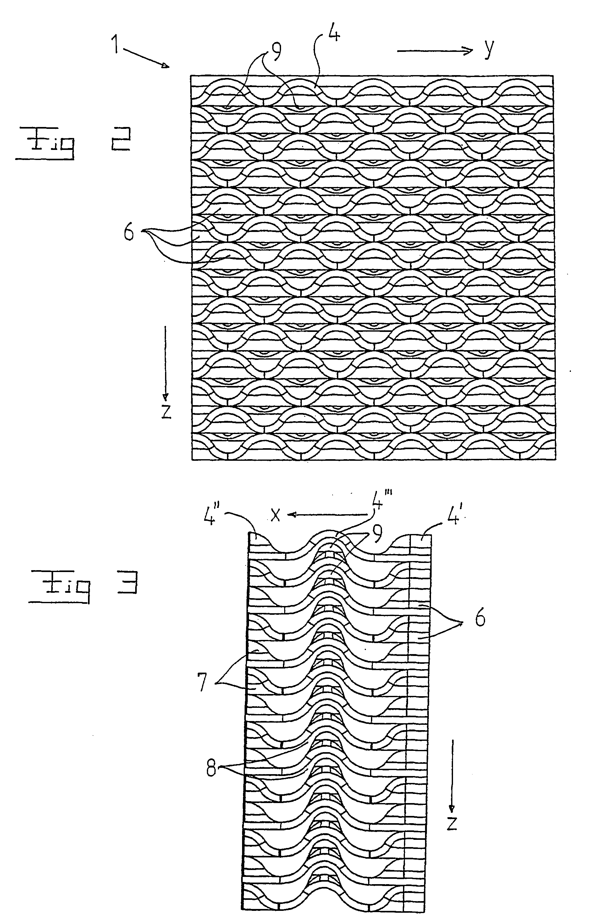
[0010] Such a filter, which may be manufactured of relatively thin sheets, has a low flow resistance since it does not require any loose components, connection members or the like which extend in the flow path. Thanks to the defined wave-shape of the sheets, a plurality of separate channels, which are arranged beside each other and which enable an efficient catching of particles in the cooling water, are obtained. The applicant has found that elongated particles are transported in the cooling water flow with an extension which substantially extends transversally to the flow direction. Such particles may consequently be caught by the filter by means of the wave-shape of the first portion. The particles, which for any reason are transported with an extension extending substantially in parallel with the flow direction, will be caught by the filter by means of the wave-shape of the third portion. The wave-shape of the sheets into directions perpendicular to each other also gives a high strength to the filter, which thus may be made self-supporting and may be mounted in for instance a fuel assembly without any frame extending around the sheets.

Problems solved by technology

If debris or other particles are permitted to follow the cooling water in the core of the reactor, these may cause defects to the cladding of the fuel rods, which may result in such defects that nuclear fuel, i.e. uranium leaks out into the cooling water.
Such a replacement is time-consuming and expensive.
Debris and other particles may of course also cause defects to other components in a nuclear plant, for instance pumps.
Particularly difficult particles are such with an elongated shape, i.e. thin wires or chips which may have a length of down to 10 mm.
The particles are vibrating in the cooling water stream and may wear the cladding of the fuel rods so that a hole arises.
Possible debris or other particles may thus be caught by such a filter.

Method used


Image

  • Filter for cooling water in a light water cooled nuclear reactor
  • Filter for cooling water in a light water cooled nuclear reactor
  • Filter for cooling water in a light water cooled nuclear reactor

Examples


Embodiment Construction

[0029] FIGS. 1-3 disclose a filter 1 for separating particles from the cooling water in a nuclear plant. The filter 1 has an inlet end 2 and an outlet end 3. The cooling water may thus flow through the filter 1 from the inlet end 2 to the outlet end 3 in a main flow direction x.

[0030] The filter 1 includes a number of sheets 4, which extend substantially in the flow direction x from the inlet end 2 to the outlet end 3. The sheets 4 are arranged beside each other and form a package of attached sheets 4. The sheets 4 are preferably manufactured of a metallic material, for instance stainless steel. The sheets 4 have a first portion 4', which extends from the inlet end 2 in the flow direction x and which has a wave-shape in a direction y extending transversally to the flow direction x. The sheets 4 also have a second portion 4", which extends from the outlet end 3 opposite to the flow direction x and which has a wave-shape in a direction y extending transversally to the flow direction x...


PUM


Abstract

The invention refers to a filter (1) for separating particle from cooling water in a nuclear plant, and a fuel assembly with such a filter. The filter has an inlet end (2) and an outlet end (3) and permits through-flow of the cooling water in a main flow direction (x). The filter includes a number of sheets (4) extending in the flow direction from the inlet end to the outlet end. The sheets are arranged beside each other and form passages for the cooling water. The sheets include a first portion (4') extending from the inlet end (2), a second portion (4'') extending from the outlet end (3), and a third portion (4''') extending between the first portion (4') and the second portion (4''). The sheets (4) have along the first portion continuous wave-shape extending in a direction (y) transversally to the flow direction (x) and along the third portion a continuous wave-shape extending in the flow direction (x).

Description

THE BACKGROUND OF THE INVENTION AND PRIOR ART[0001] The present invention refers to a filter according to the preamble of claim 1. The invention also refers to a fuel assembly according to the preamble of claim 20.[0002] The invention will be described in an application for nuclear plants for cleaning the cooling water, which flows through a nuclear reactor of a light water type, from debris and other particles. However, the invention is not limited to any particular positioning of the filter in the nuclear plant.[0003] It is important to clean the cooling water in a nuclear plant. The purpose of the cooling water is to function as a cooling fluid and a moderator in the nuclear reactor of the nuclear plant. If debris or other particles are permitted to follow the cooling water in the core of the reactor, these may cause defects to the cladding of the fuel rods, which may result in such defects that nuclear fuel, i.e. uranium leaks out into the cooling water. At larger defect, the op...

Claims


Application Information

Patent Timeline
IPC IPC(8): G21C3/30G21C3/32G21C3/322G21C3/33
CPCG21C3/3206G21C3/322Y02E30/38G21Y2004/303G21Y2002/303Y02E30/30
Inventor SODERLUND, ANDERSSODERBERG, HAKAN
Owner WESTINGHOUSE ELECTRIC SWEDEN
Learn More