Ultrasonic horn

Inactive Publication Date: 2004-04-29
ISONIX LLC
View PDF17 Cites 30 Cited by
  • Summary
  • Abstract
  • Description
  • Claims
  • Application Information

AI Technical Summary

Benefits of technology

0010] An object of the present invention is to provide an ultraso

Problems solved by technology

With more tougher cells such as heart muscle or ecoli cells, the Cup Horns typically do not induce sufficient acoustic power into the tray wells since the energy must pass through the coupling fluid and membrane of the tray itself.
These devices have typically been very unwieldy in that their length is generally that of a full wavelength of the speed of sound in titanium.
In addition, these devices could only treat up to about 1

Method used


Image

  • Ultrasonic horn
  • Ultrasonic horn
  • Ultrasonic horn

Examples


Embodiment Construction

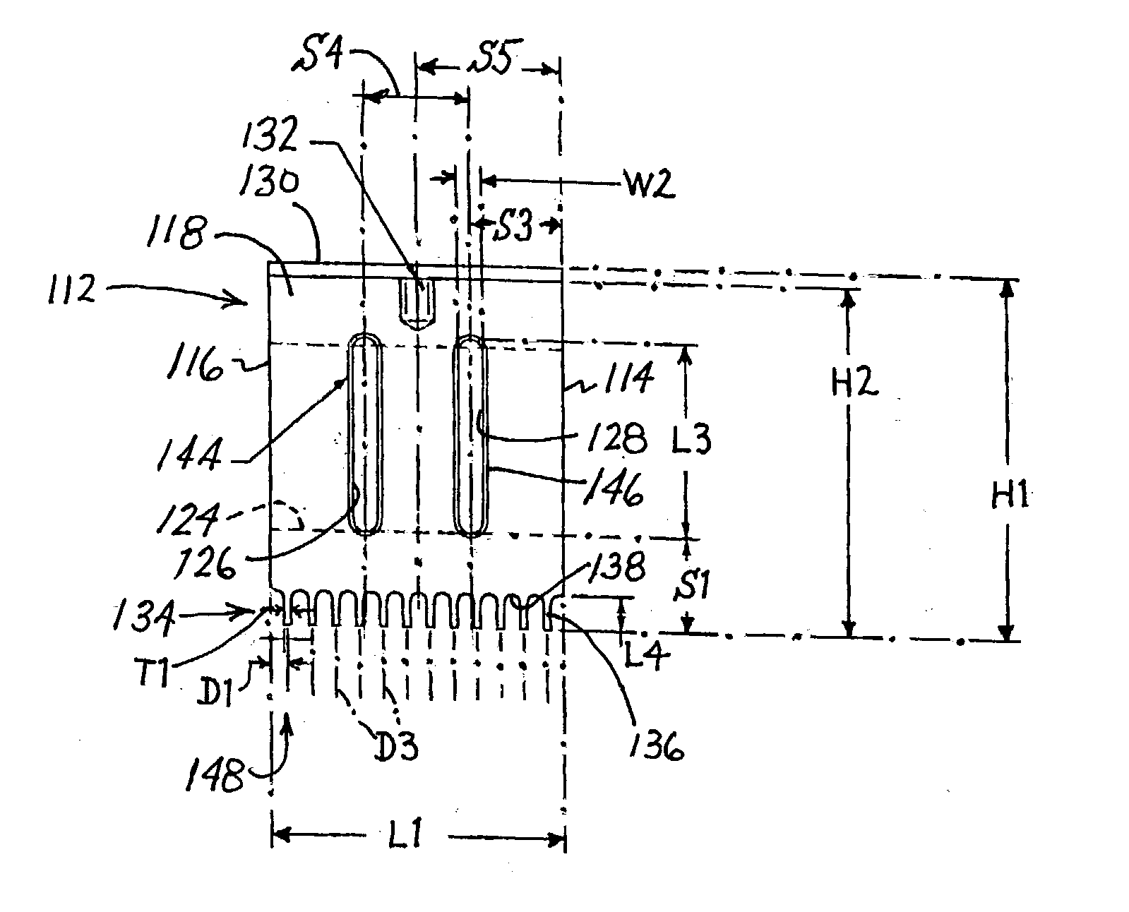
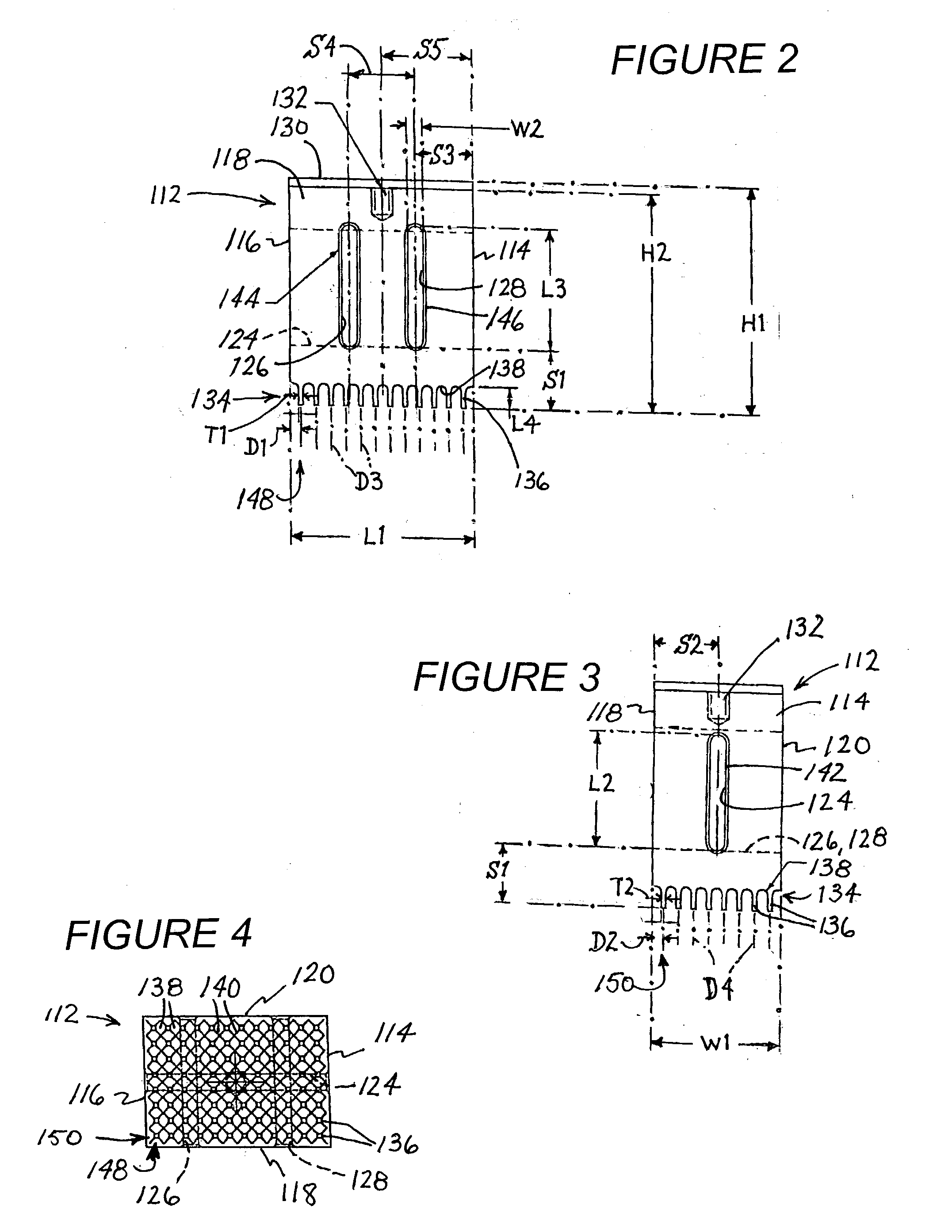
[0028] In a particular implementation of the ultrasonic horn or probe illustrated in FIGS. 2-4, block 112 is made of aluminum 7075-T6 and has a pretuned height H1 of 5.20 inches and an approximate tuned height H2 of 4.993 inches. The horn is tuned to a frequency of 20 KHz. Block 112 has a width W1 of 3.000 inches and a length L1 of 4.400 inches.

[0029] Slot 124 has a length L2 of 2.625 inches, while slots 126 and 128 have a length L3 of 2.750 inches. The slots have the same spacing S1 of 1.368 inches from the free ends or tips (not separately designated) of fingers 136. Slots 124, 126, 128 have a width W2 of 0.375 inch. Slot 124 has a spacing S2 of 1.500 inches from lateral faces 118 and 120. Slots 126 and 128 have a spacing S3 of 1.405 inches from lateral faces 116 and 114, respectively. Slots 126 and 128 have a mutual center-line spacing S4 of 1.590 inches.

[0030] Chamfers 142, 144, and 146 are at a 45.degree. angle and have a thickness (not labeled) of 0.04 inch. Stud hole 132 is s...


PUM


Abstract

An ultrasonic horn in accordance with the present invention comprises a horn body having a longitudinal transmission axis, a proximal end attachable at least indirectly to a source of ultrasonic vibrations, and a distal end with an active end face. The end face is provided with a plurality of fingers projecting parallel to one another and to the axis.

Description

[0001] This invention relates to ultrasonic vibration probes. More particularly, this invention relates to such an ultrasonic probe or horn that is particularly useful in the simultaneous sonication of biological and cellular materials disposed in multiple wells of a tray.[0002] It has been well known for decades that a probe that vibrates at ultrasonic frequencies (i.e. frequencies greater than 16,000 Hz) and has its distal end submerged under fluids will create cavitation bubbles if the amplitude of vibration is above a certain threshold. Many devices have been commercialized which take advantage of this phenomenon. An example of such an ultrasonic cellular disrupter is disclosed in the Sonicator.TM. sales catalog of Misonix Incorporated of Farmingdale, N.Y. In general, devices of this type include an electronic generator for producing electrical signals with frequencies ranging from 16 to approximately 100 KHz, a piezoelectric or magnetostrictive transducer to convert the signal ...

Claims


Application Information

Patent Timeline
IPC IPC(8): B01L9/00B06B3/00G01N35/00G01N35/02
CPCB01L9/523G01N2035/00554G01N35/028B06B3/00
Inventor MANNA, RONALD R.VOIC, DAN
Owner ISONIX LLC
Why Eureka
Try Eureka