Plate image inspection for printing prepress

a plate image and prepress technology, applied in the field of prepress technology, can solve the problems of extremely time-consuming and difficult to determine the cases of comparing data before and after proofing to perform prepress

a plate image and prepress technology, applied in the field of prepress technology, can solve the problems of extremely time-consuming and difficult to determine the cases of comparing data before and after proofing to perform prepress

US20040086156A1Inactive Publication Date: 2004-05-06DAINIPPON SCREEN MTG CO LTD

Image

  • Plate image inspection for printing prepress
  • Plate image inspection for printing prepress
  • Plate image inspection for printing prepress

Examples


Embodiment Construction

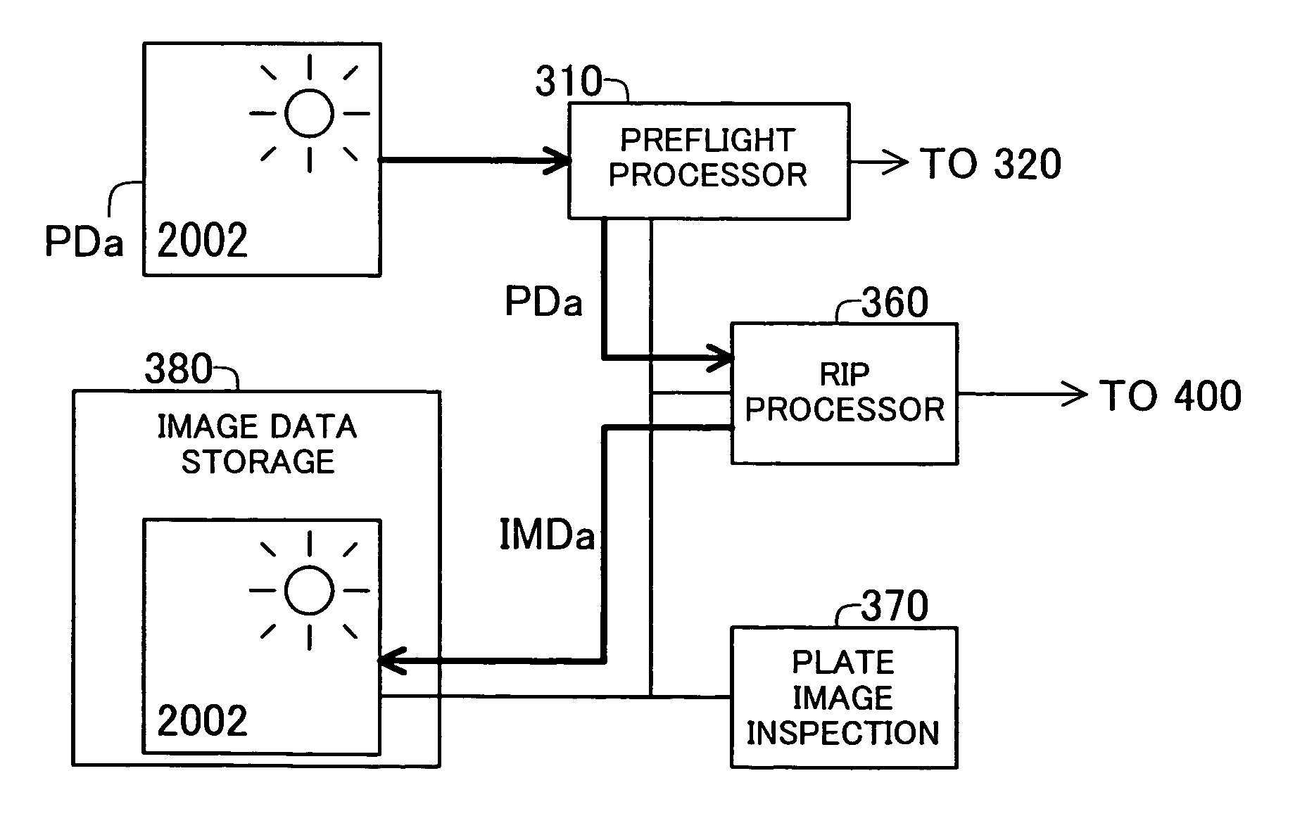
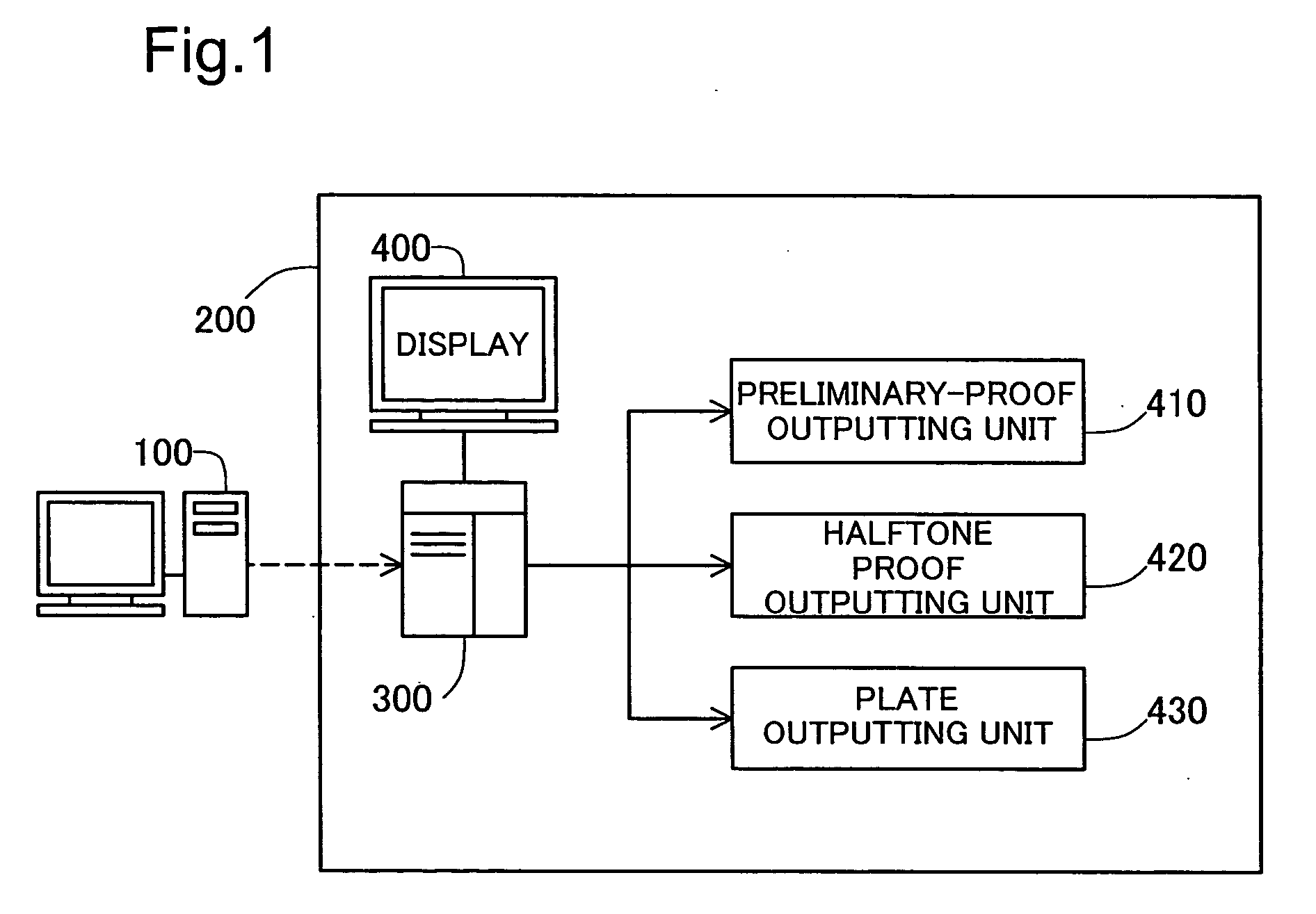
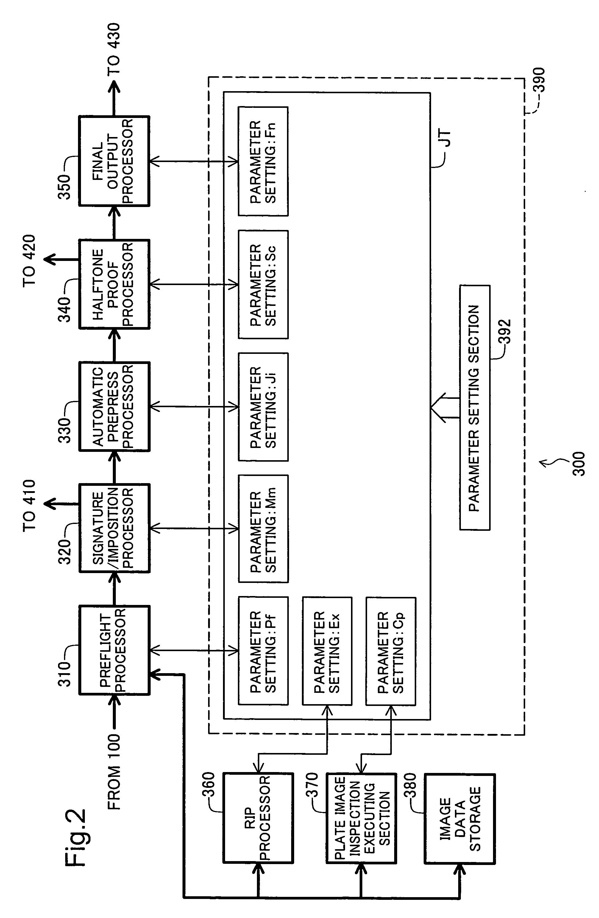
[0095] The arrangement of the prepress system is not limited to that shown in FIG. 1 or FIG. 2; any arrangement that suitably combines processors having the processing functions required for prepress is acceptable. As regards processors, rather that realizing their functions through software, an arrangement that provides independent devices for realizing their functions is acceptable. For example, an arrangement wherein an RIP processing device is connected to the workflow control system 300 (FIG. 1, FIG. 2), and RIP processing executed by the RIP processing device, is also acceptable. The display device 400 and workflow control system 300 may be connected over a network, so that users can carry out processing over the network. An arrangement wherein a printer is connected to workflow control system 300, and print image data corresponding to a printed matter is created by workflow control system 300 and sent to the printer to create printed matter is also acceptable. In this case, i...


PUM


Abstract

A prepress system comprises a raster image processor for developing first print image data to display resolution to create first raster image data, and for developing second print image data to the display resolution to create second raster image data. A plate image inspection processor executes a plate image inspection process by comparing the first and second raster image data, and displays on a display device the result of the plate image inspection process.

Description

[0001] 1. Field of the Invention[0002] The present invention relates to prepress technology for carrying out a prepress process using print data that represents a printed matter.[0003] 2. Description of the Related Art[0004] In line with progress in computer technology, computer digitization has come into widespread use even in prepress systems for commercial printing. In a digital printing prepress system, print image data (for example, PDF data or PostScript data, PostScript being a trademark of Adobe Systems Incorporated) is received, various data processing is performed on this print image data, binary plate data is prepared, and either a plate or screen film is output using this plate data. More recently, on-demand printing, wherein binary print image data is prepared in the prepress system, and this binary print image data is transferred to an on-demand printer and printed directly, has also come into use. Herein, the overall process for preparing this kind of binary plate dat...

Claims


Application Information

Patent Timeline
06 May 2004
Publication
US20040086156A1
IPC
B41C1/10; G06F3/12; B41C1/00; G06K9/00; G06K9/68; G06T7/00
CPC
B41C1/1083; G06T2207/30144; G06T7/001; H04N1/6052
Inventors
FURUKAWA, ITARU; OHARA, SETSUO