Discharge lamp

a discharge lamp and discharge tube technology, applied in the manufacture of electric discharge tubes/lamps, cold cathode manufacture, electrode systems, etc., can solve the problems of premature devitrification and blackening of discharge vessels, high lumen maintenance factor cannot be obtained, and the halogen cycle cannot operate smoothly

Active Publication Date: 2004-05-13
USHIO DENKI KK
View PDF2 Cites 7 Cited by
  • Summary
  • Abstract
  • Description
  • Claims
  • Application Information

AI Technical Summary

Benefits of technology

[0014] Due to the above described arrangement in which conditions (1) to (4) are met, within the discharge space of a discharge vessel, a suitable amount of oxygen, and moreover, only few other impurities are present. Therefore, the halogen cycle functions smoothly. In this way, the blackening and devitrification of the discharge vessel are suppressed. As a result, even in the case of operation over a long period of time, a high lumen maintenance factor is maintained.

Problems solved by technology

However, in a discharge lamp with high luminance, it is regarded as disadvantageous that the temperature of the electrodes during operation becomes rather high so that, in this way, devitrification and blackening of the discharge vessel form prematurely, and that as a result a high lumen maintenance factor cannot be obtained over a long time.
Therefore, the halogen cycle does not operate smoothly.
As a result, a high lumen maintenance factor cannot be maintained over a long period of time.
Therefore, it is difficult to control this spectral intensity with high precision.
If the value of the ratio b / a is less than 1.0.times.10.sup.-4, the amount of oxygen is unduly low, resulting in the danger that the halogen cycle is not adequately activated and that the lumen maintenance factor diminishes.
As a result, the lamp voltage drops, by which there is the danger that the operating ballast is destroyed.
Therefore, it becomes difficult to maintain a high lumen maintenance factor over a long period of time.
It therefore becomes difficult to obtain a high lumen maintenance factor over a long time.
Therefore, it becomes difficult to obtain a high lumen maintenance factor over a long time.
Therefore, it is difficult to obtain a high lumen maintenance factor over a long time.

Method used


Image

  • Discharge lamp
  • Discharge lamp
  • Discharge lamp

Examples


Embodiment Construction

[0052] The discharge lamp in accordance with the invention is described below using specific embodiments. But the invention is not limited to them.

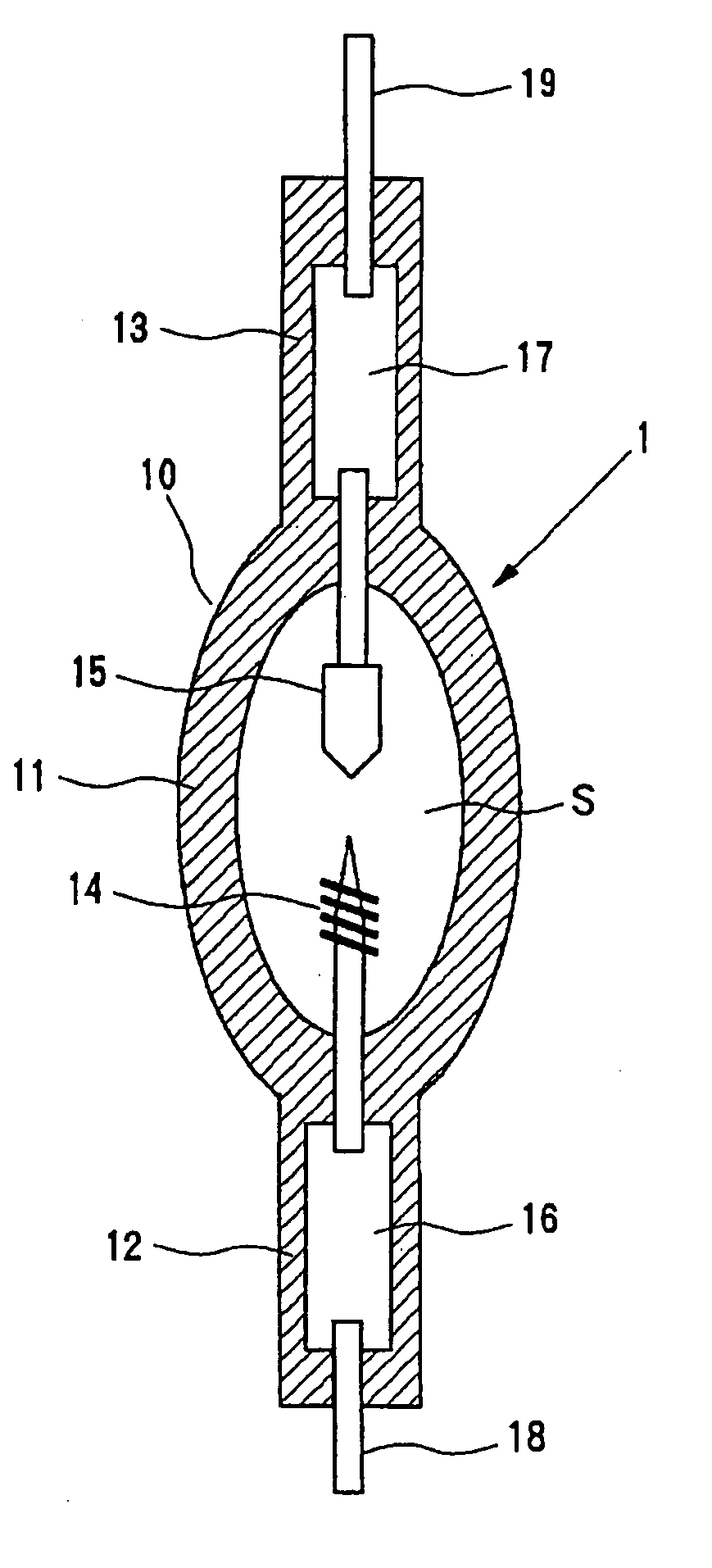
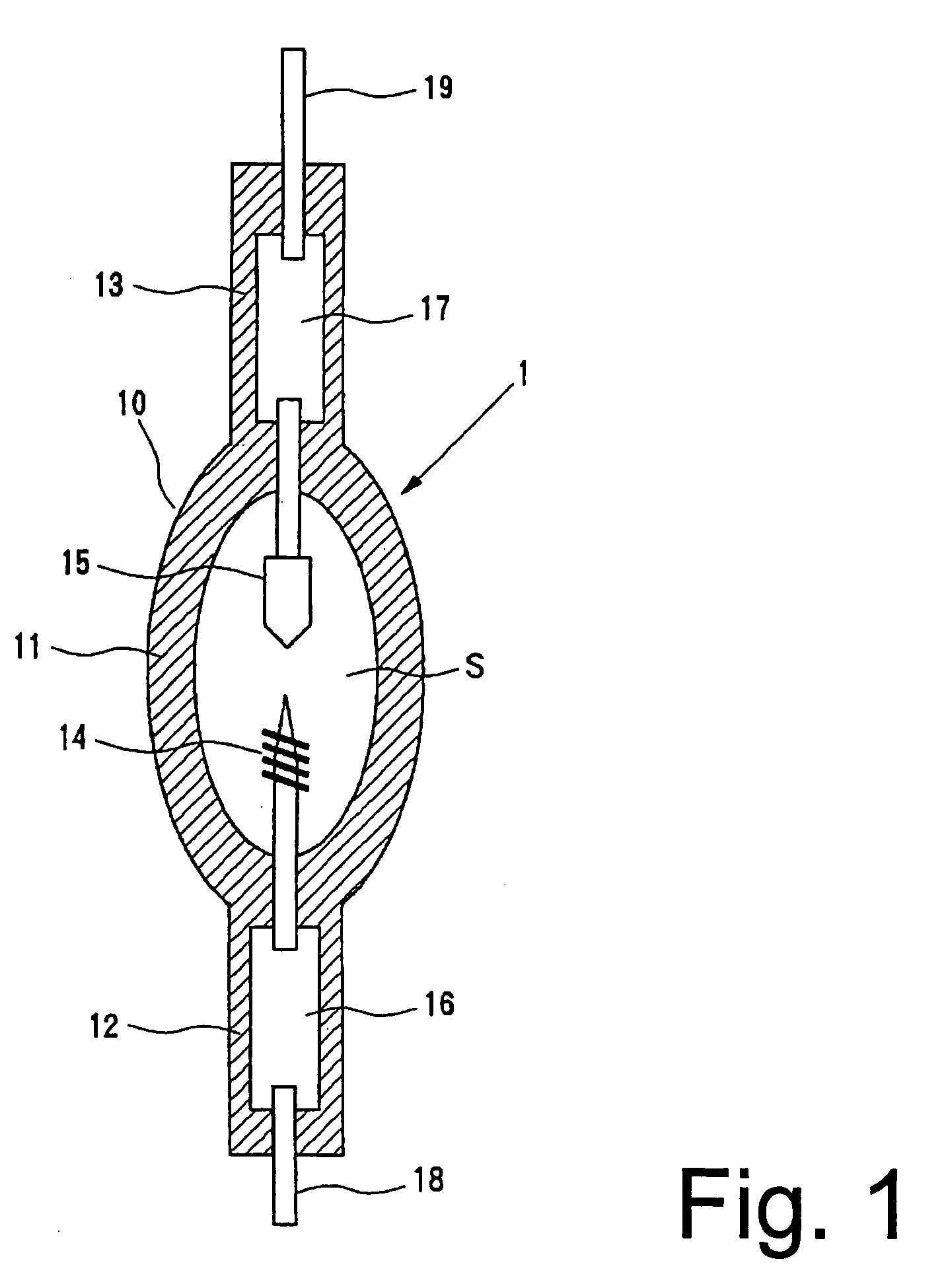
[0053] According to the arrangement shown in FIG. 1, a total of 33 types of discharge lamps containing different amounts of oxygen, different vacuum degassing conditions of the materials comprising the discharge vessel, or different heat treatment conditions of the electrodes were produced.

[0054] Particular specifications of the discharge vessel, the electrodes, the contents, and the electrical properties in these discharge lamps are described below.

Discharge Vessel

[0055] The discharge vessel (10) is made of silica glass and has a total length of 60 mm. The outside diameter of the arc tube part (11) is 10 mm. Its inside diameter is 5 mm. The volume of the discharge space (S) is roughly 80 mm.sup.3. The respective length of the hermetically sealed tube parts (12, 13) is 25 mm, and their outside diameter is 5 mm.

[0056] For vacuum degassing ...


PUM


Abstract

A discharge lamp which maintains a high lumen maintenance factor even when operated for a long time is obtained in a discharge lamp which has a silica glass discharge vessel and a pair of opposed electrodes in the discharge vessel and in which the discharge vessel is filled with at least 0.15 mg / mm<3 >mercury, a rare gas with argon as the main component, and 2x10<-4 >mumole / mm<3 >to 7x10<-3 >mumole / mm<3 >bromine by meeting the following conditions when feeding a direct current of 5 mA between the electrodes and a glow discharge produced: 1.0x10<-4><=B / A<=1.2X10<-1 > Condition (1) c / a<=1.4X10<-1 > Condition (2) d / a<=1.2X10<-2 > Condition (3) e / a<=1.4X10<-2 > Condition (4) where a is the emission intensity of the argon with a wavelength of 668 nm, b is the emission intensity of OH with a wavelength of 309 nm, c is the emission intensity of hydrogen (H) with a wavelength of 656 mm, d is the emission intensity of C2 with a wavelength of 517 nm, and e is the emission intensity of CH with a wavelength of 431 nm

Description

[0001] 1. Field of the Invention[0002] The invention relates to a discharge lamp. The invention relates especially to a discharge lamp in which the discharge vessel is filled with mercury, a rare gas, with Ar as the main component, and bromine.[0003] 2. Description of Related Art[0004] Recently, illumination devices for purposes of projection or image presentation apparatus have become common. Their light source is often a high pressure discharge lamp. In a liquid crystal projector, the light source is a discharge lamp of the short arc type because it approaches a point light source and because alignment adjustment is simple. In such a discharge lamp, there is a demand for high luminance.[0005] However, in a discharge lamp with high luminance, it is regarded as disadvantageous that the temperature of the electrodes during operation becomes rather high so that, in this way, devitrification and blackening of the discharge vessel form prematurely, and that as a result a high lumen main...

Claims


Application Information

Patent Timeline
Patent Type & Authority Applications(United States)
IPC IPC(8): H01J61/16H01J9/38H01J9/395H01J17/20H01J61/00H01J61/12H01J61/20H01J61/88
CPCH01J61/12H01J9/395
Inventor KAWAGUCHI, MASATAKAURAMOTO, MOTOKOMASASHI, DANHORIKAWA, YOSHIHIRO
Owner USHIO DENKI KK
Why Eureka
Try Eureka