Gas-discharge lamp

a gas-discharge lamp and lamp body technology, applied in the field of gas-discharge lamps, can solve the problems of shortened lamp lifetime, drop in integral light flux, and excessively high wall temperature, and achieve the effect of improving lumen maintenance and lamp life, reducing the number of lamps, and increasing heat transfer efficiency over this area conta

Inactive Publication Date: 2014-01-16
KONINKLIJKE PHILIPS ELECTRONICS NV
View PDF0 Cites 0 Cited by
  • Summary
  • Abstract
  • Description
  • Claims
  • Application Information

AI Technical Summary

Benefits of technology

[0011]An advantage of the invention is that the gap between the isolated area and the underside of the localised deformation extends over a significant planar area, as opposed to only a point or line, and the efficiency of heat transfer over this area contact is greatly increased compared to the known point or line contacts described above.
[0012]An advantage of the lamp according to the invention is that the thermal load on the upper wall of the in the discharge vessel can effectively be transferred to the outer bulb and eventually to the exterior of the lamp via the local thermal area contact. This allows more freedom in adjusting the lamp parameters. For example, if an increased light output is desired over the usual lifetime of the lamp, this can be achieved with the lamp according to the invention, since the higher temperatures at the top side are mitigated by the heat transfer over the local thermal area contact, the lumen maintenance of the lamp remains favourably high over the normal lifetime of the lamp. Alternatively, the local thermal area contact can act to prevent the temperature in the discharge vessel from reaching a level at which recrystallization would occur, such as to improve the lumen maintenance and the lifetime of lamps with normal light output.
[0013]According to the invention, the method of manufacturing a gas-discharge lamp comprises the steps of arranging a discharge vessel in an outer quartz glass envelope and forming a localised deformation of the outer envelope to create a local thermal area contact between a lower surface of the localised deformation and a corresponding isolated area on the outer surface of the discharge vessel.
[0014]An advantage of the method according to the invention is its simplicity. There is no need to alter the initial design of the discharge vessel or the outer envelope. Instead, these can be manufactured in the usual manner. The step of forming the localised deformation of the outer envelope can be carried out after the lamp has been assembled in the established manufacturing process.
[0015]The dependent claims and the subsequent description disclose particularly advantageous embodiments and features of the invention. Further embodiments may be derived by combining the features of the various embodiments described below. Features described in the context of one claim category can apply equally to another claim category.
[0016]In the following, without restricting the invention in any way, the gas-discharge lamp or “burner” is assumed to have a quartz glass discharge vessel and a quartz glass outer bulb, with a pair of electrodes arranged along a longitudinal axis to face each other across a short gap. Furthermore, it is assumed that the lamp is generally held in a horizontal position during operation, so that the discharge arc is horizontal, with the highest part of the arc and therefore also the hottest region towards the top of the discharge vessel, and the coolest temperatures towards the bottom of the discharge vessel. Without restricting the invention in any way, it is assumed in the following that the lamp is a metal-halide mercury-free xenon HID lamp, for example a D4 lamp for automotive purposes.

Problems solved by technology

Excessively high wall temperatures can damage a quartz glass vessel, since the originally amorphous quartz recrystallizes.
Over the lifetime of the lamp, recrystallization damage results in a drop in integral light flux.
Furthermore, the damaged quartz means that the lamp lifetime is shortened.
Insufficient wall temperature, on the other hand, allows the metal salts of the fill gas to condense at the coldest spot in the lamp (generally in the lower part of the discharge vessel), so that these salts are no longer available in the gas phase.
Therefore, lamp design is made difficult by the conflicting requirements of a minimum wall temperature to ensure a minimum vapour pressure of the metal-halide fill, and a maximum wall temperature to prevent damage to the discharge vessel.
However, it is normally very difficult to adjust the top and bottom temperatures independently, e.g., the temperature at the top of the discharge vessel cannot be reduced without also reducing the bottom temperature.
Unfortunately, this generally also increases the quartz temperature in the hottest part of the discharge vessel, resulting in recrystallization and, ultimately, a corresponding deterioration in the lumen maintenance of the lamp.
However, the smaller gap achieved in this manner is restricted to a geometric point or line, and the resulting local heat transfer will not be very effective.
Furthermore, such lamp designs are complicated to realise, and therefore also more expensive, since additional steps must be taken in the manufacturing process to achieve an off-centre position of the discharge vessel in the outer bulb.

Method used


Image

  • Gas-discharge lamp
  • Gas-discharge lamp
  • Gas-discharge lamp

Examples


Embodiment Construction

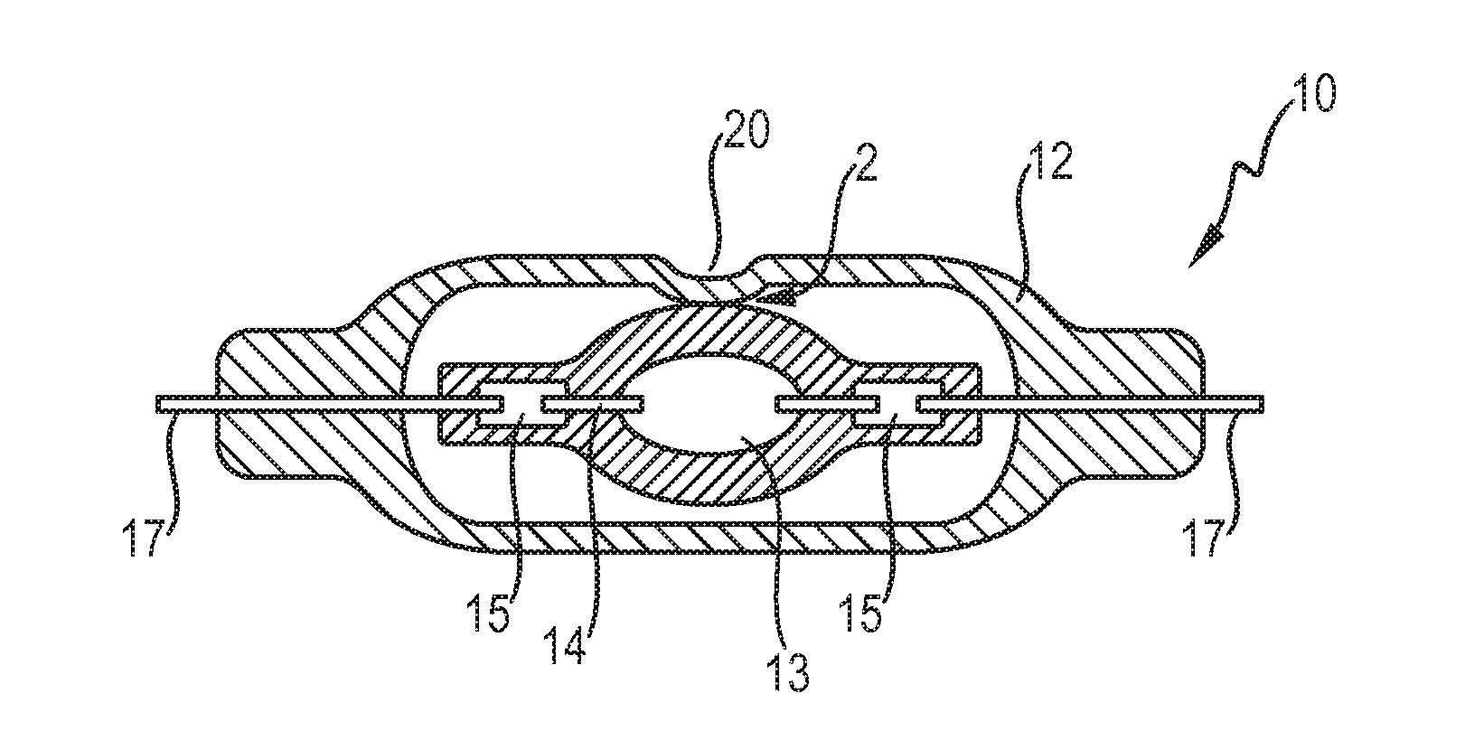
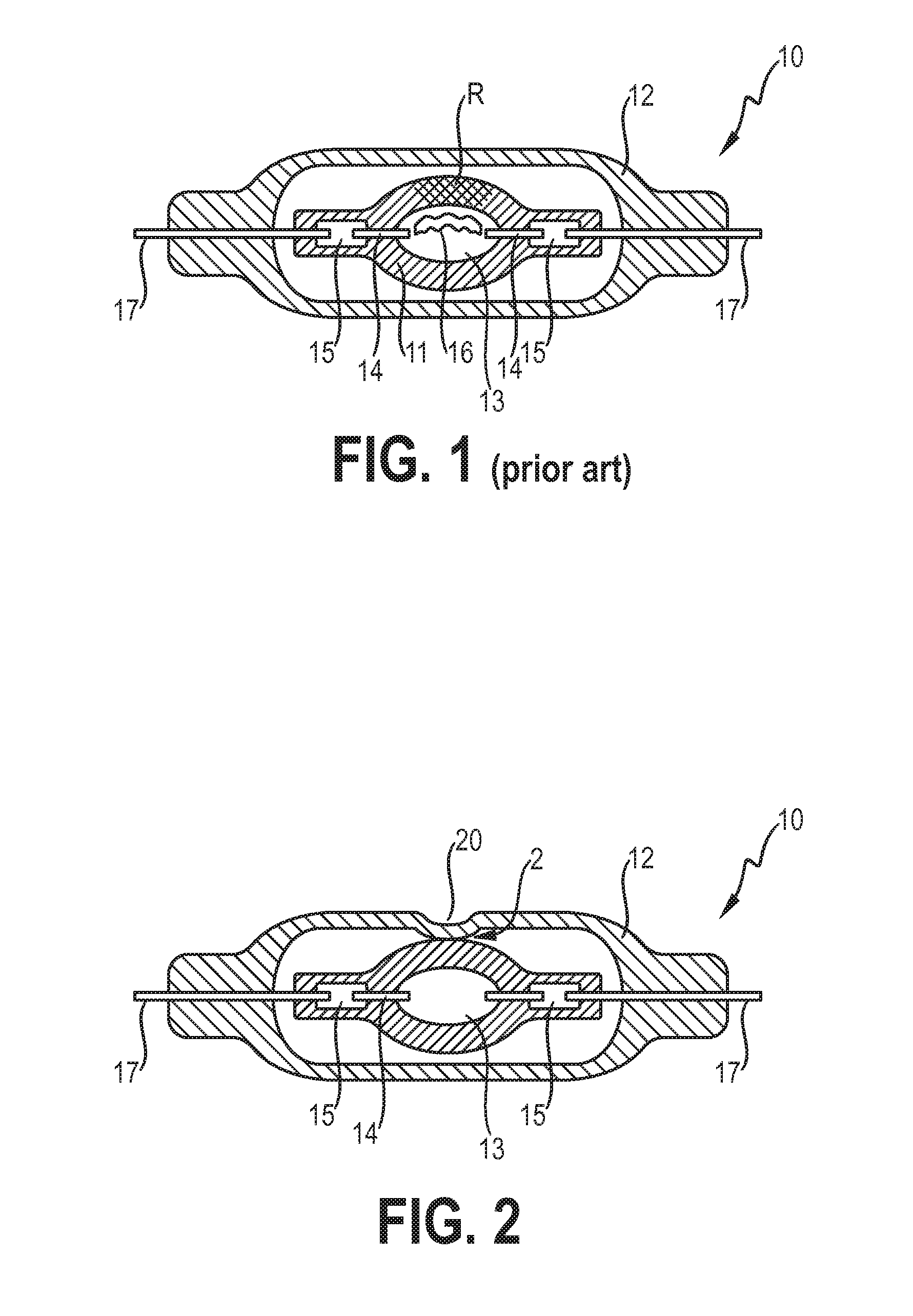
[0037]FIG. 1 shows a prior art gas-discharge lamp 10 with a discharge vessel 11 arranged in an outer envelope 12. A pair of electrodes 14 protrudes into the discharge vessel 11. To mitigate thermo-mechanical stress owing to the high temperatures obtained during operation, an electrode 14 is usually connected to an exterior lead 17 by a flat molybdenum foil 15 enclosed in a pinch end of the discharge vessel 11. During operation, a discharge arc 16 is established between the electrode tips. Due to convection and the plasma nature of the discharge arc, the temperature in the upper region of the discharge vessel 11 is higher than in the lower region of the discharge vessel 11. For the reasons mentioned in the introduction, a high wall temperature in the lower vessel region is desired, since this ensures that sufficient metal salts are available in the plasma so that a high light output can be achieved. Because the wall temperature in the upper region is always higher than in the lower r...


PUM


Abstract

The invention describes a gas-discharge lamp (1) comprising a discharge vessel (11) arranged in an outer quartz glass envelope (12), which gas-discharge lamp (1) comprises a local thermal area contact (2) between a lower surface (21) of a localised deformation (20) of the outer envelope (12) and a corresponding isolated area (22) on the outer surface (23) of the discharge vessel (11). The invention also describes a method of manufacturing a gas-discharge lamp (1), which method comprises the steps of arranging a discharge vessel (11) in an outer quartz glass envelope (12); forming a localised deformation (20) of the outer envelope (12) to create a local thermal area contact (2) between a lower surface (21) of the localised deformation (20) and a corresponding isolated area (22) on the outer surface (23) of the discharge vessel (11).

Description

FIELD OF THE INVENTION[0001]The invention describes a gas-discharge lamp and a method of manufacturing a gas-discharge lamp.BACKGROUND OF THE INVENTION[0002]High-intensity gas-discharge (HID) lamps are used for applications in which a very bright, compact and intense source of light is required. For example, HID lamps are used in automotive front-lighting applications, since they can be used to generate a bright front beam that satisfies the relevant regulations. An HID lamp comprises an outer envelope (or ‘outer bulb’) enclosing a discharge vessel (or ‘inner bulb’) which can be made of glass or ceramic, in which two electrodes are arranged, facing each other across a short gap. During operation, an electric discharge arc is established. The quality of the light produced by the lamp may be governed by the fill gas composition in the discharge vessel. Metal halides are used to improve the luminous efficacy of the lamp and to control the colour point of the light. During operation, pl...

Claims


Application Information

Patent Timeline
Patent Type & Authority Applications(United States)
IPC IPC(8): H01J61/33H01J9/24
CPCH01J61/33H01J9/247H01J61/34H01J61/523H01J61/827H01J61/32
Inventor HECHTFISCHER, ULRICHGIESE, HERMANN
Owner KONINKLIJKE PHILIPS ELECTRONICS NV
Why Eureka
Try Eureka