
Turbo blood pump

Inactive Publication Date: 2004-05-13
JMS CO LTD
View PDF5 Cites 22 Cited by
  • Summary
  • Abstract
  • Description
  • Claims
  • Application Information

AI Technical Summary

Benefits of technology

[0017] By using the turbo blood pump of the present invention, various problems mentioned above can be solved. Firstly, even in a liquid transferring pump with a small size (amount of blood to be filled is small), a large flow amount of liquid can be transferred. And by increasing the rotational speed, it is easy to adjust and maintain the amount of liquid to be transferred. Second, even if the liquid transferring pump operates at practically high rotational speed, the hemolysis degree is small, thus reducing the damage to the body. As a result, it is possible to be applied to a long time extracorporeal circulation.

Problems solved by technology

However, when the centrifugal pumps are used in a clinical application, there have been the following problems to be solved.
Firstly, the centrifugal blood pumps have a problem as to the amount of blood to be filled.
As a result, the amount of blood for extracorporeal circulation is increased, thus burdening a patient more.
In such a case, it is not possible to realize the reduction of hemolysis (damage to blood), etc.
Furthermore, if a centrifugal pump, in which the standard such as rotational speed, amount of liquid to be transferred, amount of liquid to be filled, etc. is set for an adult patient, is used for a child patient or a patient who cannot tolerate a large amount of blood circulation, the pump has to be used at the lower rotational speed, and it is difficult to adjust and maintain the amount of liquid to be transferred.
Furthermore, not a few of conventional centrifugal pumps have a structure in which blood tends to stagnate in the central portion of the lower surface of the impeller.
When such a centrifugal pump is used, there arise some problems in that thrombus tends to be formed, and it is difficult to use such a pump for a long-time extracorporeal circulation, etc.
Firstly, even in a liquid transferring pump with a small size (amount of blood to be filled is small), a large flow amount of liquid can be transferred.
However, it becomes difficult to secure a flow path, which may cause hemolysis.
Furthermore, if the number of the vanes 6 is increased, the manufacture becomes difficult.
On the contrary, the distance is too large, there arises a problem, for example, the amount of blood to be filled is increased.
However, in a case where such a shaft seal is provided, it is necessary to consider taking measures against blood leakage, thus causing some problems, for example, the heating of the shaft seal and the formation of thrombus.

Method used


Image

  • Turbo blood pump
  • Turbo blood pump
  • Turbo blood pump

Examples


Embodiment Construction

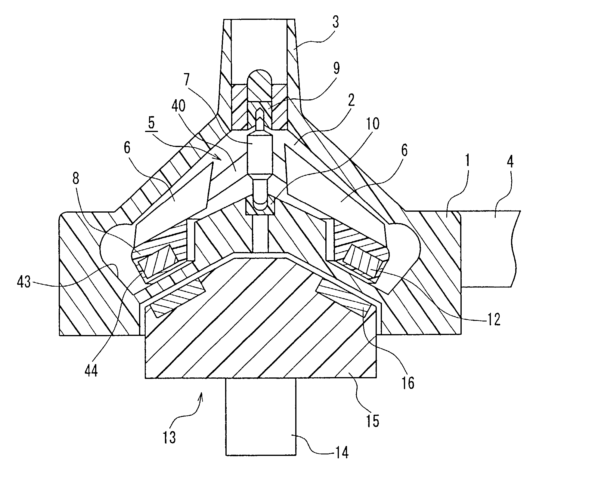
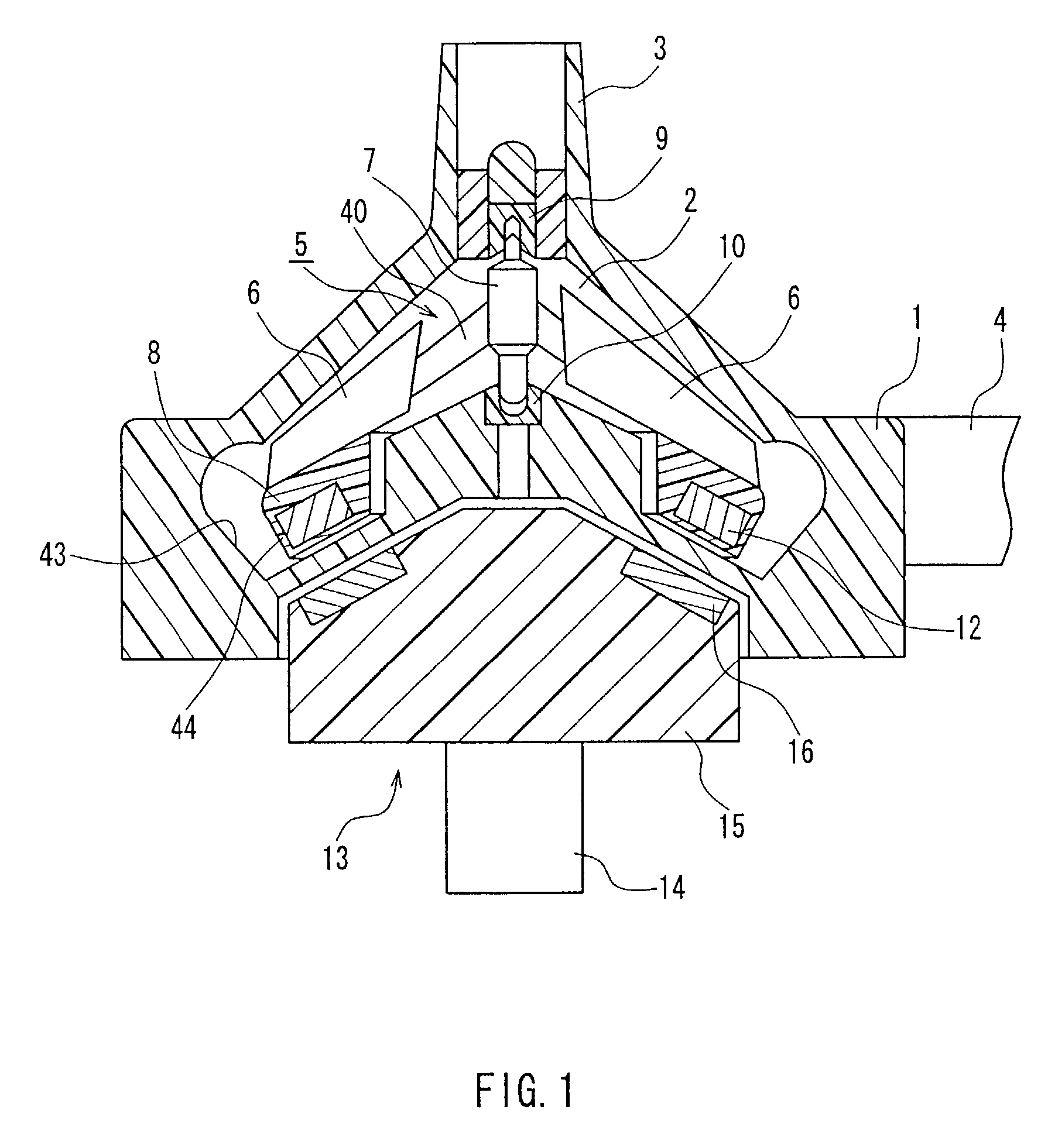
[0059] FIG. 6 is a cross-sectional view showing another example of the turbo blood pump of the present invention. In FIG. 6, components to which the same reference numbers are given as in FIG. 1 are configured similar to the components shown in FIG. 1. The turbo blood pump shown in FIG. 6 is configured in the same manner as the turbo blood pump shown in FIG. 1 except that the shape of the inside the housing 45 is different from the shape of the inside the housing 1.

[0060] In the turbo blood pump shown in FIG. 6, the outer diameter and the height of the housing 45 are set to be 58 mm and 56 mm, respectively. The weight of the housing 45 is set to be 43 grams. Furthermore, the amount of blood to be filled in the pump chamber 2 is 20 mL. The housing 45 and the impeller 5 are formed of resin materials such as polycarbonate. Furthermore, the rotation shaft 7 is formed of stainless steel, and the upper bearing 9 and the lower bearing 10 of the rotation shaft 7 are formed of PEEK mentioned...


PUM


Abstract

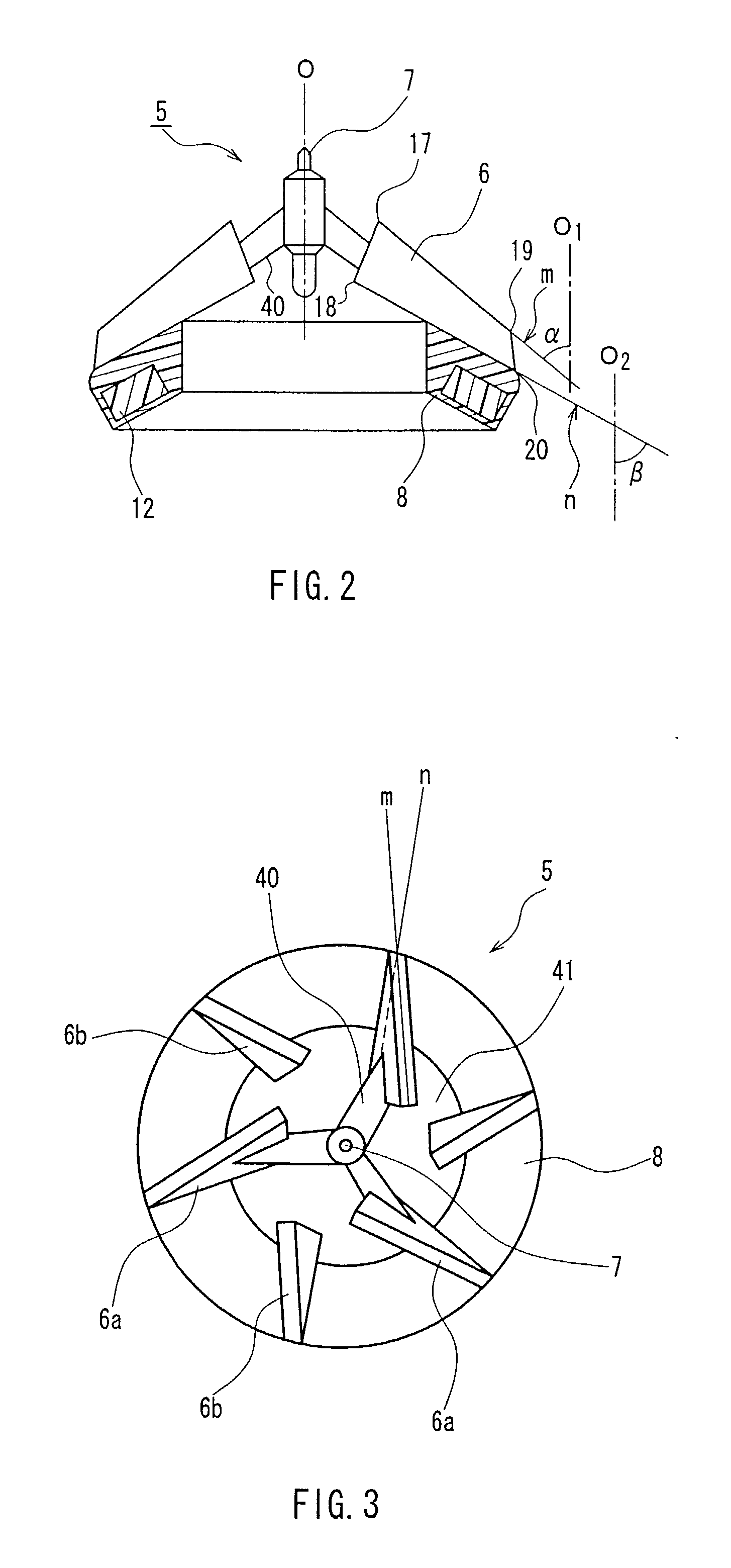
A turbo blood pump having a small size, that is, a small amount of blood to be filled and capable of adjusting and maintaining the slight amount of flow, and a turbo blood pump in which hemolysis is not likely to occur even if it is used at a practically high rotational speed necessary to obtain a predetermined discharging ability. The turbo blood pump to be used includes a housing having an inlet port and an outlet port; and an impeller disposed rotatably in the housing; wherein the impeller includes at least a rotation shaft and an annular connection portion to which the plural vanes are attached. The vane is manufactured so that an inlet side part is in the skew position with respect to an outlet side part.

Description

[0001] 1. Field of the Invention[0002] The present invention relates to a liquid-transferring pump for medical use. More specifically, the present invention relates to a turbo blood pump for transferring blood by providing blood with thrust by the rotation of an impeller.[0003] 2. Description of the Related Art[0004] Conventionally, in extracorporeal circulation in an operation using an artificial heart lung apparatus, etc., a roller blood pump has been used mostly. Recently, however, centrifugal blood pumps increasingly have been used. This is because, as compared with roller blood pumps, the centrifugal blood pumps (turbo blood pumps) have various advantages, for example, little damage to blood, etc. Furthermore, as compared with a driving portion of a conventional large size roller blood pump, the centrifugal blood pump may have a smaller driving portion. Therefore, the centrifugal blood can be disposed and carried easily.[0005] However, when the centrifugal pumps are used in a c...

Claims


Application Information

Patent Timeline
IPC IPC(8): A61M60/109A61M60/216A61M60/419A61M60/806A61M60/818F01D1/02F04D29/18F04D29/24
CPCA61M1/101F01D1/02A61M1/1036F04D29/242F04D29/183A61M60/419A61M60/216A61M60/109A61M60/806
Inventor ARAKI, KENJIANAI, HIROFUMIMAEDA, HIROYUKISATO, MASAFUMI
Owner JMS CO LTD
Learn More