Polymer fiber tubular structure having kinking resistance

a technology of polymer fiber and tubular structure, which is applied in the direction of spray discharge apparatus, turning machine accessories, drawing profiling tools, etc., can solve the problems of kinking of artificial vessels fabricated using conventional electrospinning, affecting the performance of the machine, and affecting the effect of the effect of kinking

Inactive Publication Date: 2004-05-20
NICAST LTD
View PDF99 Cites 41 Cited by
  • Summary
  • Abstract
  • Description
  • Claims
  • Application Information

AI Technical Summary

Problems solved by technology

Production of polymer fiber tubular structures is particularly difficult when such tubular structures are required to have radial tensile strength sufficient to resist tearing and collapse in response to a pulsating pressure while at the same time maintain several elastic properties, such as the ability to bend without breaking and without kinking, in order to allow conformation to a complex geometry.
However, an artificial vessel fabricated using conventional electrospinning does not withstand kinking, and further reinforcement of the final product is necessary.
This feature prevents the employment of tube corrugation, since such structure affects the blood flow and may cause thrombogenesis.
On the other hand, in the vascular system, application of various adhesives is highly undesirable.
Hence, the above mentioned techniques, to prevent collapse of the vessel lumen are inapplicable.
Electric forces of repulsion within the capsules lead to a drastic increase in hydrostatic pressure.
Thus, small diameter products, may exhibit limited radial strength.
Moreover, the existence of an opposite volume charges in the inter-electrode space, decreases the electric force on the fibers, thus resulting in a large amount of fibers accumulating in the inter-electrode space.
Such an effect may lead to a low-efficiency process of fiber coating, and may even result in a total inability of fibers to be collected upon precipitation electrode 22.
This is because polycondensation is not exercised at all such that the chemical interaction between the agent and the polymer is absent, and further due to the low concentration of charge control agent employed.

Method used


Image

  • Polymer fiber tubular structure having kinking resistance
  • Polymer fiber tubular structure having kinking resistance
  • Polymer fiber tubular structure having kinking resistance

Examples


Embodiment Construction

[0119] Reference is now made to the following example, which together with the above descriptions, illustrate the invention in a non limiting fashion.

[0120] Tubular structures, 6 mm in diameter and 200 mm in length were manufactured.

[0121] A polyurethane of Carbotan 3595 blend was purchased from The Polymer Technology Group Incorporated. This polymer was provided with aromatic urethane hard segment, polycarbonate and silicone co-soft segments and surface-modifying end groups. Silicone-urethane copolymers demonstrate a combination of high mechanical properties with oxidative stability, low rate of hydrolytic degradation biostabillity and tromboresistance. In addition, this polymer is characterized by a high fiber forming ability.

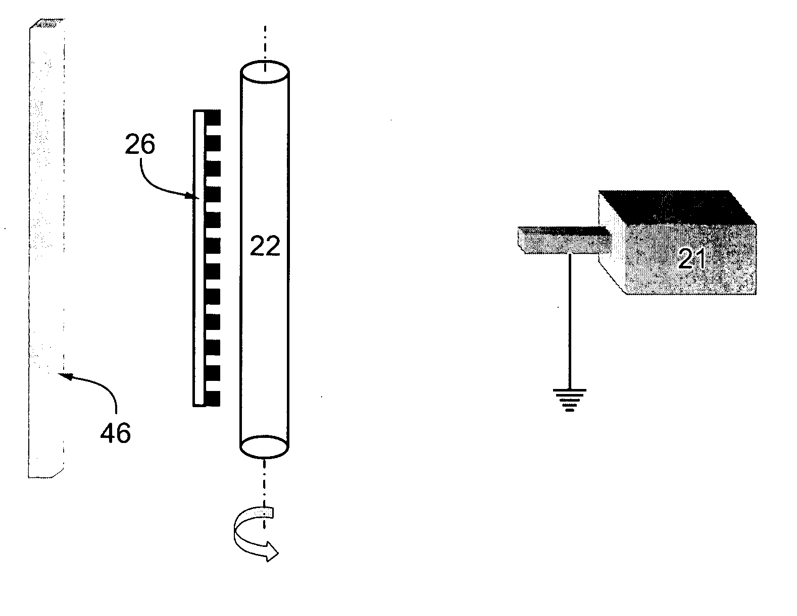
[0122] A rod, 6 mm in diameter and 300 mm in length was used as a precipitation electrode, and its central 200 mm portion was coated at ambient temperature (24.degree. C.). The precipitation electrode was rotated at an angular velocity of 100 rpm.

[0123] A spi...


PUM

PropertyMeasurementUnit
electric fieldaaaaaaaaaa
widthaaaaaaaaaa
temperatureaaaaaaaaaa

Abstract

An apparatus for forming a tubular structure from a liquefied polymer, the apparatus comprising: (a) a dispenser for dispensing the liquefied polymer; (b) a precipitation electrode being at a first potential relative to the dispenser, the precipitation electrode being designed and constructed for generating a polymeric shell thereupon; and (c) a mechanism for increasing a local density of the polymeric shell in a plurality of predetermined sub-regions of the polymeric shell, thereby to provide a tubular structure having an alternating density in a longitudinal direction.

Description

FIELD AND BACKGROUND OF THE INVENTION[0001] The present invention relates to a method and apparatus for manufacturing tubular structures via electrospinning and, more particularly, to a method and apparatus for manufacturing a polymer fiber tubular structure having improved kinking resistance. The present invention further relates to tubular structures having improved kinking resistance.[0002] In many medical and industrial applications, tubular structures made from polymer fibers are used as, e.g., vascular prostheses, shunts and the like. Production of polymer fiber tubular structures is particularly difficult when such tubular structures are required to have radial tensile strength sufficient to resist tearing and collapse in response to a pulsating pressure while at the same time maintain several elastic properties, such as the ability to bend without breaking and without kinking, in order to allow conformation to a complex geometry.[0003] When an elastic tubular product bends, ...

Claims


Application Information

Patent Timeline
Patent Type & Authority Applications(United States)
IPC IPC(8): A61F2/00A61F2/06A61F2/82A61L15/16A61L17/00A61L27/00A61L27/50A61L27/56B29C67/20C08F2/00D01D5/00D01D5/04D01D5/08D04H1/70D04H3/07D04H3/16
CPCA61F2/06Y10T428/1393A61F2/82A61F2/91A61F2002/072A61F2250/0023A61F2250/0067A61L27/507A61L27/56B29C67/20D01D5/0007D01D5/0069D01D5/0092D01D5/18D04H1/70D04H3/07D04H3/16A61F2210/0076Y10T428/1372Y10T428/13Y10T428/139A61F2/07D04H1/728Y10T442/614
Inventor DUBSON, ALEXANDERBAR, ELI
Owner NICAST LTD
Why Eureka
Try Eureka