Slide holder for an automated slide loader

a slide loader and slide technology, applied in the direction of supporting apparatus, microscopes, optics, etc., can solve the problems of not being able to interface with free-standing microscopes, not being able to manufacture stand-alone automated slide loaders, and limited to manual operation, so as to achieve accurate positioning and maximise the scan area. the effect of the ability

Inactive Publication Date: 2004-06-17
LEICA BIOSYST MELBOURNE
View PDF11 Cites 39 Cited by
  • Summary
  • Abstract
  • Description
  • Claims
  • Application Information

AI Technical Summary

Benefits of technology

0020] By using the defined combination of fixed locaters and movable locating and clamping means, the slide does not need to be initially placed on the slide holder with any great accuracy since movement of the locating and clamping means ensures that the slide is always accurately positioned against the fixed locaters as the slide is clamped.
0021] The fixed locaters and the locaters on the slide locating and clamping means preferably engage only the edge regions, and preferably only the edges, of the slide to thereby maximise the scan area capable of being viewed by the microscope during examination of each slide.

Problems solved by technology

There is no stand-alone automated slide loader in the market that loads and unloads slides to and from an external, free-standing optical microscope.
It is not possible with these designs to interface to free-standing microscopes.
a) they are limited to manual operation only. They require the user to manually open the clamping mechanism, accurately position the slide on the slide holder, and then release the clamping mechanism. Consequently, such methods are not suited to automated scanning systems as they require constant attendance from laboratory staff to load and unload slides.
b) the positional accuracy achieved by manually locating slides is not always guaranteed.
a) positional accuracy of the slide under the microscope is not guaranteed either by manual or robotic positioning;
b) considerable modifications to a microscope stage are required to accommodate vacuum lines (a vacuum pump is also required but can be mounted away from the microscope).
c) to obtain adequate clamping (suction) of a slide, both ends of the slide would require vacuum thereby reducing the effective scan area on the slides. Therefore critical features on the slide may be missed.
d) Vacuum chucks and associated plumbing can obstruct the optical path between a microscope's condenser and objective lens.
a) the slide holder can only be used manually as it requires the user to manually place the slide against one slide retainer before the slide could be clamped down.
b) the slide holder requires a user to use two hands to position a slide correctly; one hand to hold the slide against the fixed locaters on the back and the slide retainer, and the other hand to clamp the slide. It is not designed to automatically locate the slide.
c) the positional accuracy in the x-axis is dependent on human placement of the slide.
d) the positive force required to clamp the slide into position may lead to crack and chipping of slides.

Method used


Image

  • Slide holder for an automated slide loader
  • Slide holder for an automated slide loader
  • Slide holder for an automated slide loader

Examples


Embodiment Construction

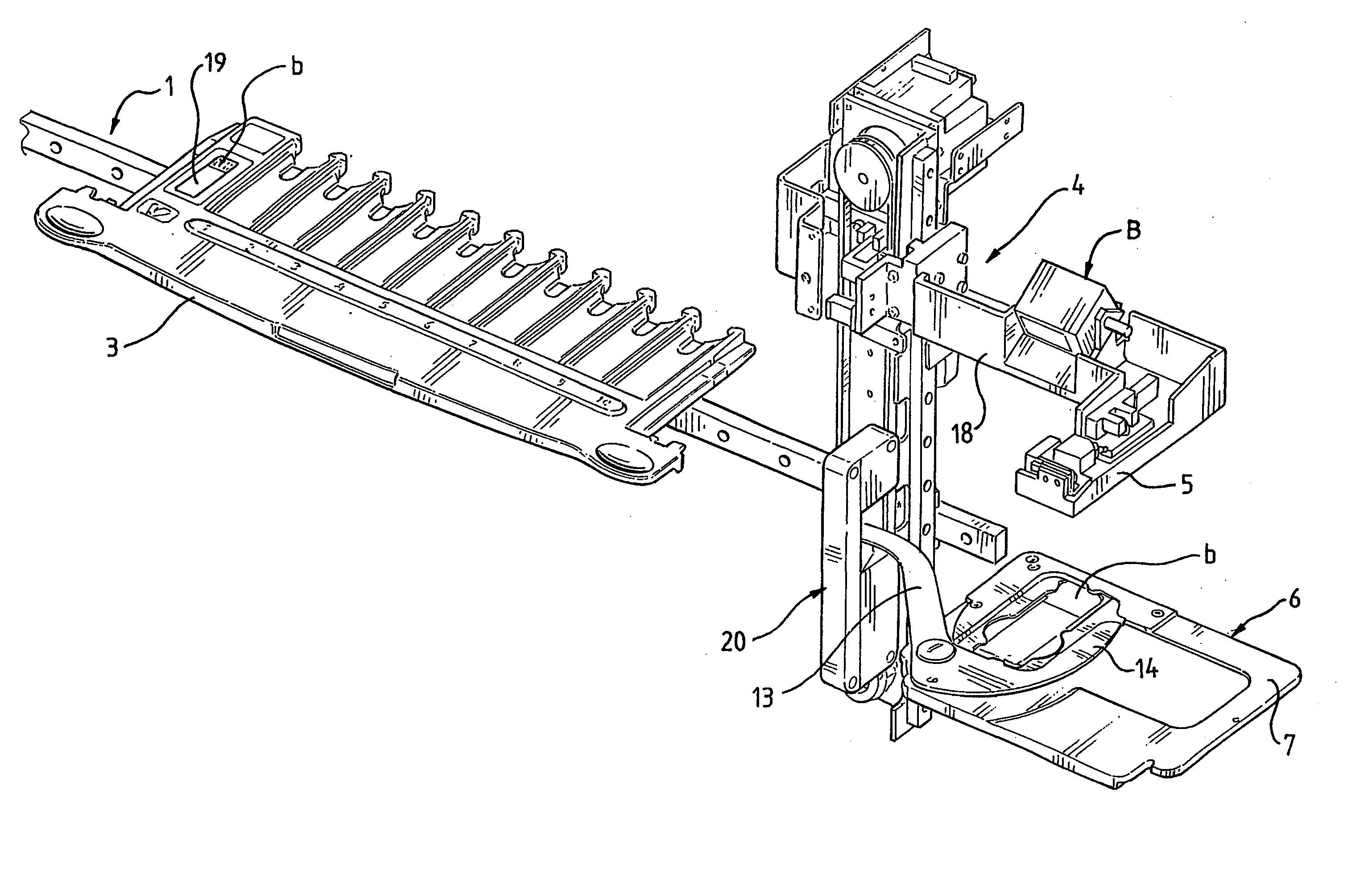
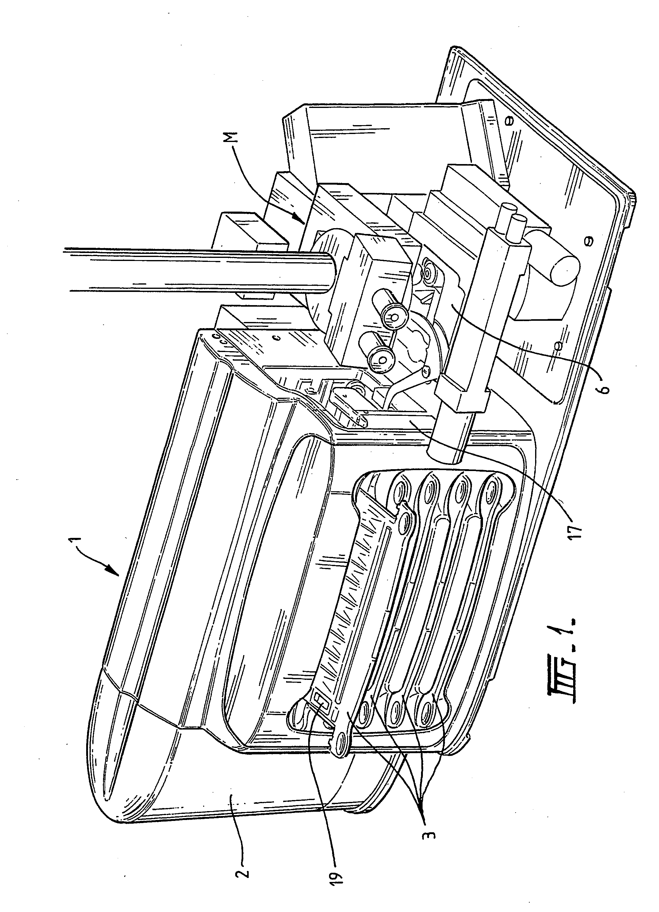
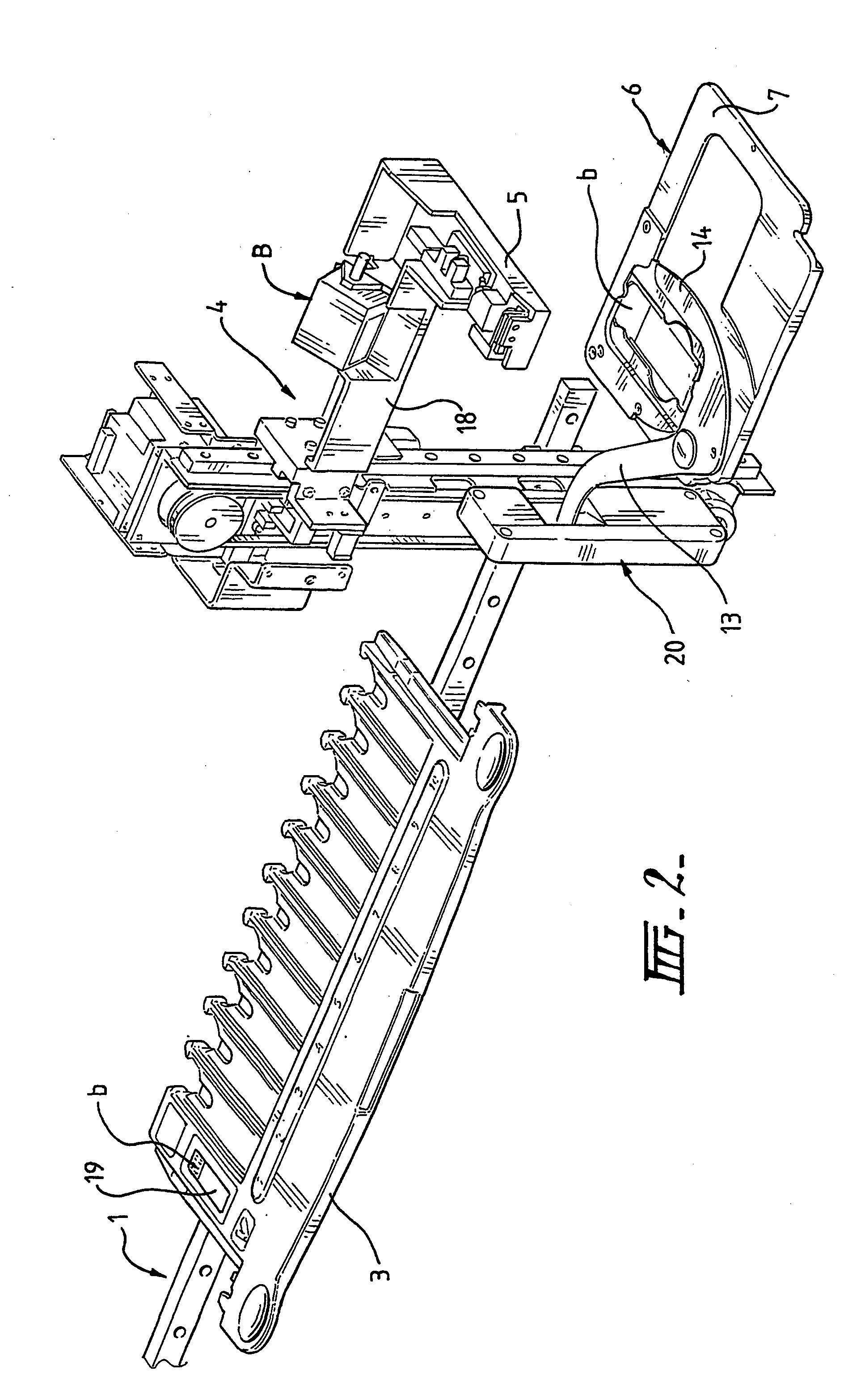
[0037] Referring firstly to FIGS. 1 and 2 of the drawings, the side loader 1 includes a housing 2 within which a multiplicity of slide supporting trays 3 are located in a vertical stack. A slide transfer means 4 (FIG. 2) includes a robot head 5 incorporating a suction cup (not shown) with an associated vacuum supply which enables automated lifting of slides 19 from a selected tray 3 followed by depositing of the slides on a slide holder 6 carried by a motorised translation stage of a microscope assembly M. The transfer means 4 is mounted within the slide loader 1 for independent horizontal and vertical movement which enables the robot head to be automatically moved in response to a command from an external controller (not shown) to select a designated slide from one of the trays 3 for loading onto the slide holder 6. An arm 18 supporting the robot head 5 also supports a barcode reader B which operates to read a barcode area b on each slide as it is picked up and returned to the tray...


PUM

PropertyMeasurementUnit
areaaaaaaaaaaa
image processingaaaaaaaaaa
opticalaaaaaaaaaa

Abstract

A slide holder (6) for use with a microscope to accurately locate a slide (19) in position under the microscope has a pivotal lever (13) having a clamping and locating portion (14) with abutments (15) and (16) which bear on respective edges of the slide when it is in the clamped position. Further abutments (10) on a fixed angular plate (9) locate the other edges of the slide. The slide holder is adapted for mounting on a slide translation stage of a slide loader (1) which includes a stationary sensor block (20) positioned to engage the lever (13) when the slide holder moves from its inspection or scanning position under the microscope to a loading/unloading position. The slide translation stage includes a robotic head for lifting and depositing slides and the translation stage includes a bar code reader to read a bar code on the slide.

Description

[0001] This invention relates to slide holders for use with an automated slide loader.[0002] In recent years there has been a rapid growth in the reported use of automated image processing systems to analyse images obtained from video and digital cameras mounted on optical microscopes. However, the benefits of using such systems have been offset by the need to manually load and unload microscope slides on the microscope.[0003] There is no stand-alone automated slide loader in the market that loads and unloads slides to and from an external, free-standing optical microscope. Current processes of loading and unloading slides are either performed manually or require a dedicated instrument that already has a built-in microscope and imaging system.[0004] There are several patents that describe systems to automatically load and unload slides onto microscopes including U.S. Pat. No. 4,248,498 (Georges), and U.S. Pat. No. 4,501,495 (Faulkner). These patents describe systems whereby the slid...

Claims


Application Information

Patent Timeline
Patent Type & Authority Applications(United States)
IPC IPC(8): B01L9/00G01N35/00G02B21/26G02B21/34
CPCB01L9/52B01L2200/025B01L2300/0822G02B21/34G01N2035/00138G02B21/26G01N2035/00089
Inventor HENDERSON, CHESTER JOHNMORRIS, STEPHEN COLLINGSREILLY, IAN DONALDVOM, EDUARDO
Owner LEICA BIOSYST MELBOURNE
Why Eureka
Try Eureka