
Device for determining the condition of oil

a technology for determining the condition of oil and oil, which is applied in the direction of lubrication indication devices, lubrication elements, instruments, etc., can solve the problems of affecting the characterization of this oil property, affecting the reliability of the evaluation of the oil condition, and insufficient knowledge of these variables alon

Inactive Publication Date: 2004-07-01
ROBERT BOSCH GMBH
View PDF7 Cites 14 Cited by
  • Summary
  • Abstract
  • Description
  • Claims
  • Application Information

AI Technical Summary

Benefits of technology

[0005] It is particularly advantageous that the device is usable onboard in a motor vehicle. Therefore, the motor oil may be monitored long-term, giving rise to the positive concomitants such as that of an oil change only when necessary and the like. It is also advantageous that the concentration of volatile constituents is a function of the total base number of the oil. Therefore, from the measurement of the concentration of the volatile constituents, it is possible on one hand to infer the total base number, and in a further step, to infer the condition of the motor oil. It is also advantageous if the device includes a semiconductor gas sensor having a sensitive layer, the sensitive layer including metal oxides. It is thereby possible to provide the semiconductor gas sensor in a particularly cost-effective manner and nevertheless in a manner that it is sufficiently sensitive for the volatile gas constituents of the motor oil to be determined. Furthermore, it is advantageous if the sensitive layer includes metal oxides of the metals Sn, W, Zn, Fe, Mo and / or Cr with admixtures of less than 1% of metals and / or metal oxides from the group of metals Co, Ni, Mo, Re, Zn, Cr, Al, Ce and / or Mn, and with admixtures of less than 1% of metals from the group of metals Ag, Au, Pt and / or Pd. It is thereby possible, by a different fashioning of the sensitive layer, to either especially optimize it for different situations, or to provide a widely usable sensitive layer having a sufficient sensitivity for many measuring situations, which means a sensitive layer of this type may be produced particularly inexpensively. It is furthermore advantageous if the device has an SAW (surface acoustic waves) sensor or a BAW (bulk acoustic waves) sensor or a chemiluminescence sensor. It is thereby advantageously possible to use alternative sensor principles for the sensor of the present invention, i.e., for the example device of the present invention. Another advantage is that the example device may have a first membrane which is impermeable for oil, but is permeable for the volatile constituents. It is thereby possible, using simple means, to employ a gas sensor according to the present invention for determining the condition of oil. Moreover, it is advantageous if the volatile constituents are acetaldehyde, acetone, acetic acid and / or benzaldehyde. This permits particularly easy detectability using the sensitive layer according to the present invention. Moreover, it is advantageous if the device includes a gas compartment which is separated from an oil-containing region by the first membrane. It is thereby possible to keep the device particularly stable over its service life, because the gas-sensitive layer is not soiled or impaired by contact with the oil. It is also advantageous that the first membrane is moistened by oil.

Problems solved by technology

It is disadvantageous that such laboratory analyses cannot be carried out in vehicles while driving, which would permit a continuous monitoring of the condition of the lubricants.
However, the knowledge of these variables alone is not adequate for a reliable evaluation of the oil condition.
The fact that the acid and basic constituents in motor oil are, primarily, not present in dissolved form, additionally hinders the characterization of this oil property.
In contrast to aqueous solutions, whose acid content may easily be indicated using the pH value, the conditions are more difficult to determine for oils.
That the measurement of the indicated volatile compounds is indeed possible in principle in the laboratory, e.g., with the aid of gas chromatography or mass spectroscopy, changes nothing in the fact that this is not possible for the practical use of determining the condition of oil during the running operation of a motor vehicle or a combustion engine, but rather may only be carried out using bulky and complex measuring devices.

Method used


Image

  • Device for determining the condition of oil
  • Device for determining the condition of oil

Examples


Embodiment Construction

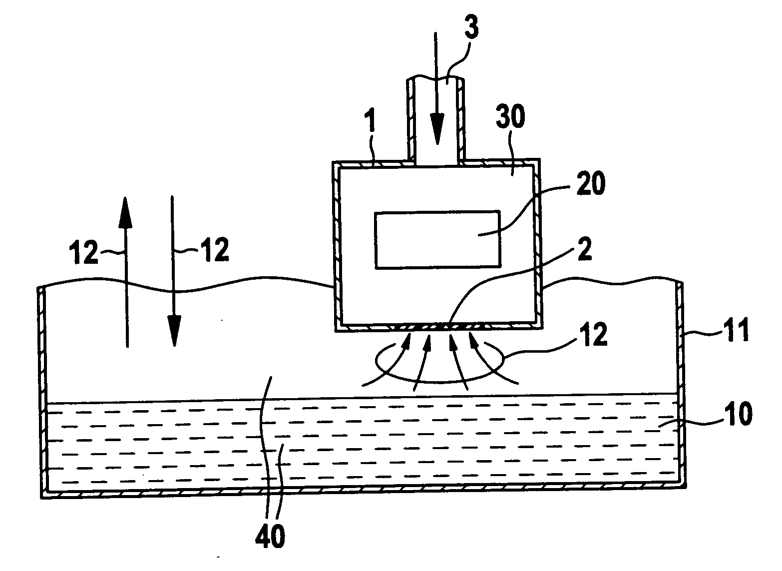
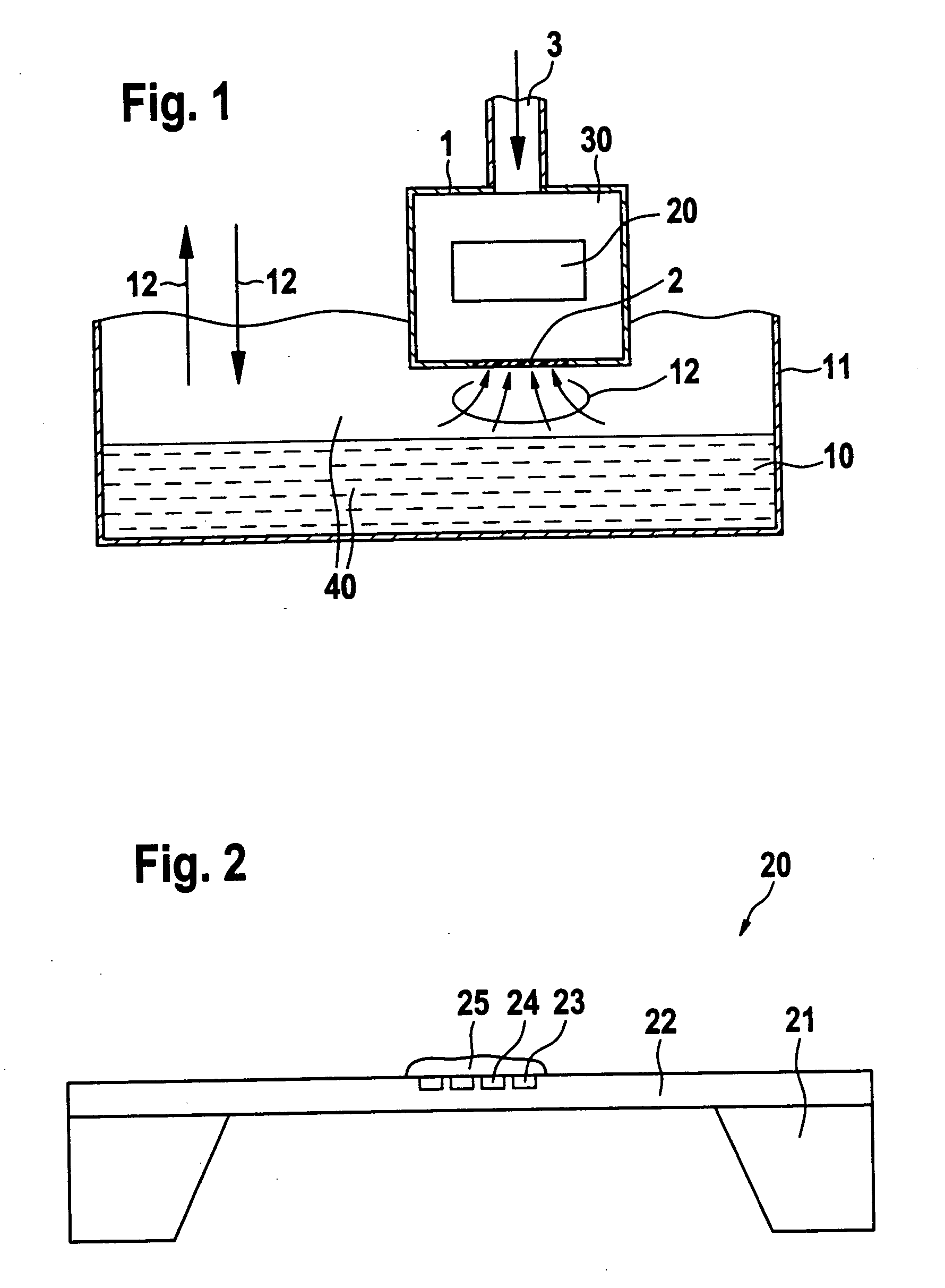
[0009] FIG. 1 shows a configuration in principle of device 1 according to an example embodiment of the present invention. Device 1 includes a gas sensor 20 which, according to the present invention, is provided in particular as a semiconductor gas sensor, and therefore is also designated in the following as semiconductor gas sensor 20. Gas sensor 20 is shown in greater detail in FIG. 2. Moreover, device 1 includes a gas compartment 30 in which gas sensor 20 is located.

[0010] In device 1 according to the present invention, gas compartment 30 is separated from an oil-containing region 40 by a first membrane 2. First membrane 2 is provided as a so-called oil-repellent membrane. This means that although first membrane 2 is permeable for volatile constituents, which are provided in FIG. 1 with reference numeral 12 and which are present in oil-containing region 40, first membrane 2 is impermeable for oil, which is provided in FIG. 1 with reference numeral 10 in an oil reservoir 11.

[0011] ...


PUM

PropertyMeasurementUnit
temperatureaaaaaaaaaa
concentrationaaaaaaaaaa
permeableaaaaaaaaaa

Abstract

A device for determining the concentration of volatile constituents of motor oil is described.

Description

[0001] The present invention is based on a device for determining the condition of oil.BACKGROUND INFORMATION[0002] Analysis methods are known for analyzing the ageing of lubricants in combustion engines, e.g., in motor oil, which may be carried out in a laboratory. To that end, a number of physical and physical-chemical measuring methods are used which in each case evaluate one specific ageing aspect of the oil sample being examined. It is disadvantageous that such laboratory analyses cannot be carried out in vehicles while driving, which would permit a continuous monitoring of the condition of the lubricants.[0003] In accordance with an example embodiment of the present invention, it is possible to evaluate the condition of the oil onboard, since the oil condition may be continuously monitored. For example, no sampling is necessary for measuring the state of the oil. Conventional sensors are based predominately on simple physical measuring principles such as the measurement of the...

Claims


Application Information

Patent Timeline
Patent Type & Authority Applications(United States)
IPC IPC(8): F01M11/10G01N27/12G01N33/28
CPCF01M11/10G01N33/2841G01N27/12
Inventor JAKOBY, BERNHARDKRUMMEL, CHRISTIAN
Owner ROBERT BOSCH GMBH
Learn More